Eureka AIR delivers breakthrough ideas for toughest innovation challenges, trusted by R&D personnel around the world.

Aquatic floating and transportation method of ultra-large type component

A super-large, component technology, used in transportation and packaging, special-purpose ships, ships, etc., can solve problems such as damage to the structure of the component itself, inability to adjust the left and right heels, and increase the difficulty of floating, to reduce resistance and increase fore and aft defense. Crash-safe float function, easy to control and adjust effects

Active Publication Date: 2007-03-14
WUCHANG SHIPBUILDING IND
View PDF1 Cites 10 Cited by
  • Summary
  • Abstract
  • Description
  • Claims
  • Application Information

AI Technical Summary

Problems solved by technology

A key issue in water transportation of super-large components is to maintain the balance of component operation to prevent the air cushion from leaking and failing. This patent is to adjust the balance of component floating by supplementing air in different air chambers, and the left and right of component floating The balance is adjusted by setting the left and right air chambers. For large components with no longitudinal partitions in the structure to form the left and right air chambers, there is a problem that the left and right heels cannot be adjusted during floating transportation. This will not only greatly increase the difficulty of floating transportation, but the situation is serious. will lead to the failure of floating
However, adding longitudinal partitions on large components to form left and right air chambers will not only damage the structure of the components to a certain extent, but also greatly increase the cost of component fabrication and assembly.

Method used

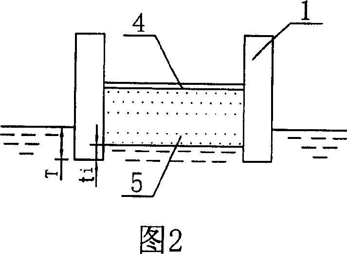
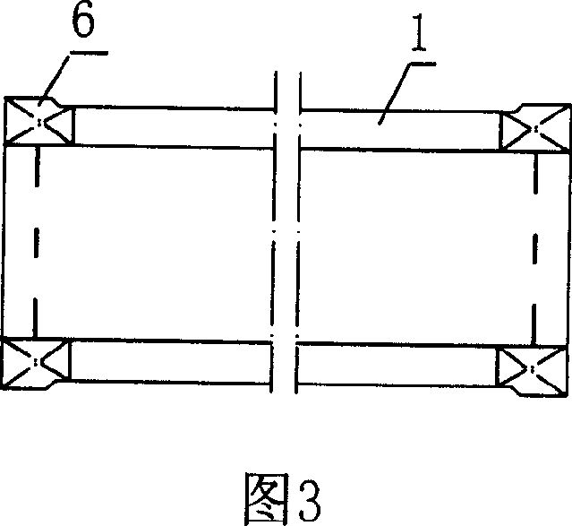

Image

  • Aquatic floating and transportation method of ultra-large type component
  • Aquatic floating and transportation method of ultra-large type component
  • Aquatic floating and transportation method of ultra-large type component

Examples


Embodiment Construction

[0025] The embodiment of the present invention will be further described below in conjunction with the accompanying drawings. For the overall floating of the main longitudinal beam member of the ship-bearing compartment of the Three Gorges ship lift in the Yangtze River, a long steel welded structure includes a main body with box-shaped cross-sections arranged on both sides. Longitudinal beam 1, both ends of the main longitudinal beam are closed to form a sealed cabin, and airtight ballast water tanks are arranged at the two ends of the two main longitudinal beams, thereby forming four independent ballast water tanks 6 at the front, rear, left, and right , the ballast water tank is connected with the ballast pump water system, which is used to adjust the heel and pitch of the floating body. The ballast pumping system is arranged in the box-shaped main longitudinal girder and beam, and the ballast water tank is communicated with the floating water surface through connecting pipe...


PUM


Abstract

The invention relates to waterborne floating transporting method used when construct super sized component such as dams for the power stations and bridges. Its program is: detecting fairways, forming sealed compartment with the cross beam and / or the longitudinal beam of trunk section of super sized component, forming inflatable air chamber with the within web of said cross and longitudinal beam; connecting the inflatable air chamber with compressed air source, putting the super component in waterborne fairways; aerifying the inflatable air chamber and forming air cushion between it and the surface and leading to the giant component floating on the water; regarding the towboat as power and driving the super component into waterways to floating and transporting. Its features are: installing independent ballast water tank on the both ends of longitudinal beam on the both sides of super component, ballast water tank is linked with the ballast pumping system to adjusting the ballast water of each ballast water tanks. The adaptability to component structure of the invention is better, adjustment and balance is easy and convenient to completing when in water run-time, so the overall floating and transporting performance of super component is more perfect.

Description

technical field [0001] The invention relates to a method for floating on water for super-large components such as construction of power station dams and bridges, in particular to a method for floating on water as a whole of the main longitudinal beam of a ship-bearing compartment of a dam ship lift, which is an improvement on the existing method for floating on water further improvement. Background technique [0002] One of the characteristics of large steel components used in the construction of hydropower dams and bridges is their large size and heavy weight. For example, the ship lift compartment used for hydropower dams is more than 100 meters long and 100 meters wide. From a few meters to more than 20 meters, the height is ten meters, and the weight can reach several thousand tons; the second feature is that the cross-section of the longitudinal beam and part of the beam is a hollow box structure, and has the structural characteristics of a low outer periphery below the...

Claims


Application Information

Patent Timeline
Patent Type & Authority Applications(China)
IPC IPC(8): B63B38/00B65G51/00B65G7/00
Inventor 严俊胡广宇彭祖洋
Owner WUCHANG SHIPBUILDING IND
Why Eureka
Eureka Blog
Learn More