Magnetic rheopectic solution fan clutch

A magneto-rheological fluid and clutch technology, which is applied in fluid clutches, clutches, machines/engines, etc., can solve the problems that cannot be applied to small and small spaces, large spaces, etc., and achieve compact structure, promote heat exchange, and prolong service life. Effect

Inactive Publication Date: 2007-03-14
SHIJIAZHUANG RAILWAY INST
View PDF4 Cites 22 Cited by
  • Summary
  • Abstract
  • Description
  • Claims
  • Application Information

AI Technical Summary

Problems solved by technology

Their input shafts and output shafts are generally on the same straight line, occupying a large space, and cannot be applied to occasions with small spaces.

Method used


Image

  • Magnetic rheopectic solution fan clutch
  • Magnetic rheopectic solution fan clutch

Examples


Embodiment Construction

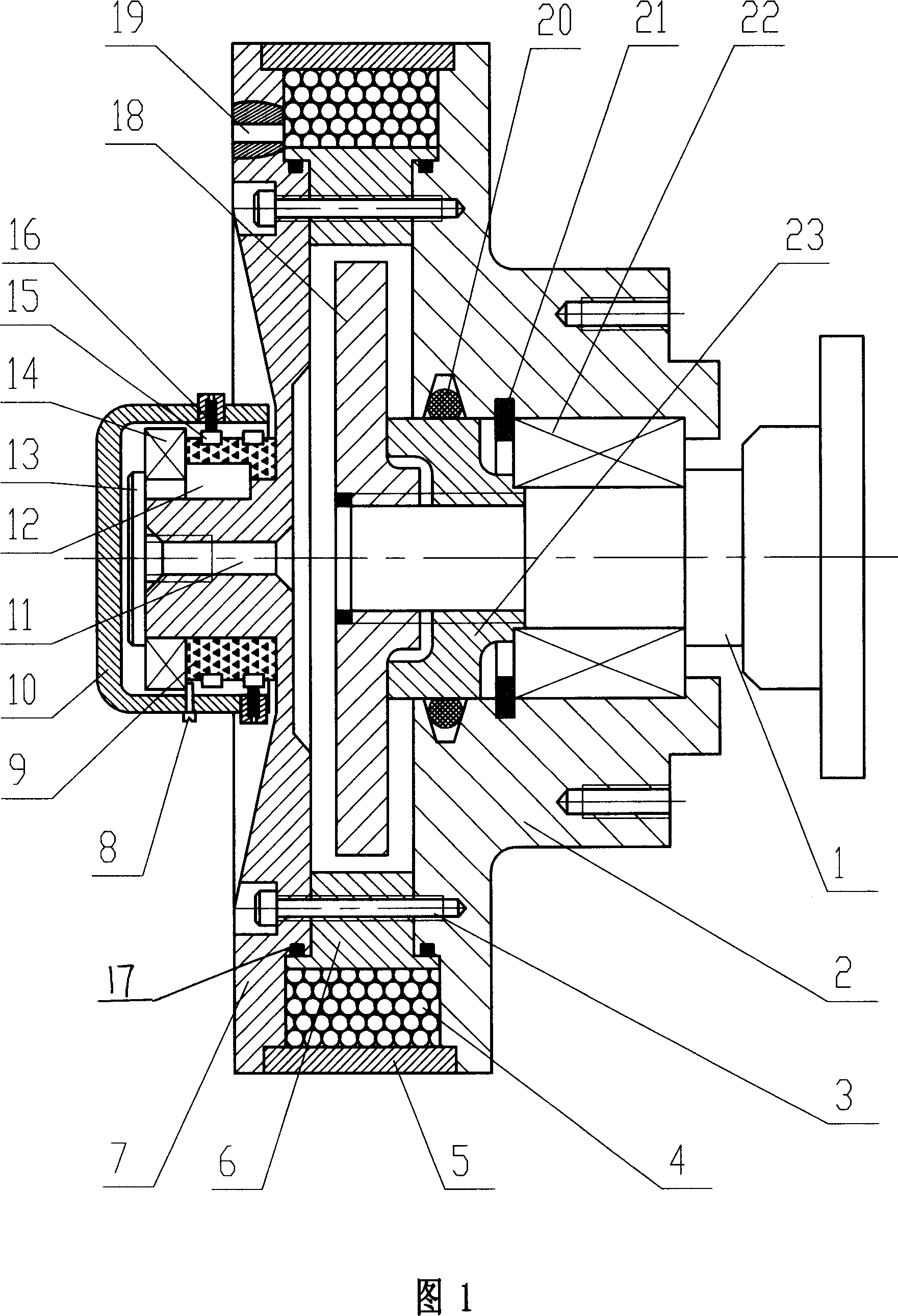
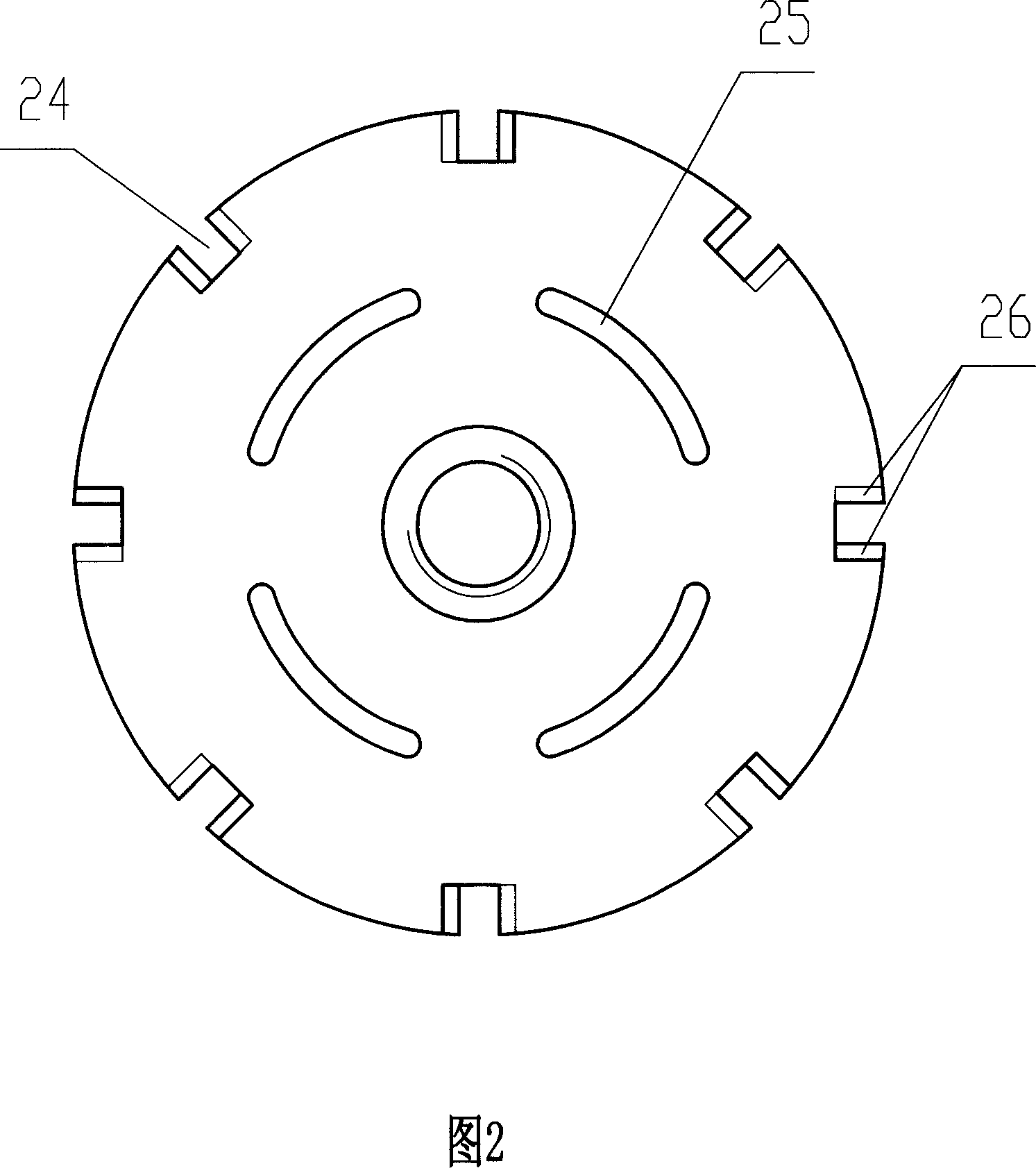
[0024] As can be seen from Fig. 1 and Fig. 2, the present invention has following structure:

[0025] On the power transmission shaft 1 of the present invention, bearing 22, bearing retaining ring 21, axle sleeve 23 and active piece 18 are installed successively, wherein axle sleeve 23 and active piece 18 are to be connected on the transmission shaft 1 by screw thread, and the rotation direction of its screw thread and The rotation direction of the driving shaft 1 is opposite; a clutch housing is installed outside the bearing 22, and the clutch housing as a whole is used as a passive part, and its housing is divided into a front housing 7 and a rear housing 2, and the rear housing 2 is installed on the bearing 22 , an O-ring seal 20 is arranged on the outside of the shaft sleeve 23, and the O-ring seal 20 is embedded in the clutch rear housing 2; the clutch front housing 7 is fixedly connected with the clutch rear housing 2 through the connecting bolt 3 as a whole. Between the...


PUM


Abstract

The invention discloses to a fan clutch with magnetic rheologic fluid, comprising active plate, passive plate, magnetic rheologic fluid, drive shaft, excitation coil, bearing and sealing device. Drive shaft is connected with active plate set in hollow cavity of passive plate. Passive plate is divided into frontal and rear shell. Sealing cover, excitation coil and outer ring of clutch are set orderly from inner to outer between frontal and rear shell. Rheologic fluid is injected into the cavity formed by active and passive plate and excitation coil supplies power by carbon brush assembled at the central axis of frontal shell. Drive shaft is connected with engine and passive plate is connected with fan. The invention is a circular clutch with magnetic rheologic fluid. The structure is very compact and it is applied in narrow space between cooling fan and water tank of engine. Rheologic fluid is flowing iteratively in the space between active and passive plate, which is advantaged to eliminate heat and prolongs the service life of rheologic fluid.

Description

technical field [0001] The invention relates to a transmission mechanical device, in particular to a magneto-rheological fluid clutch. Background technique [0002] At present, liquid viscous transmission, as an emerging technology, has attracted more and more attention. Liquid viscous transmission is generally divided into cylindrical oil film, disc oil film, conical oil film and combined oil film according to the shape of the mechanism of the shearing effect of the oil film. Due to the presence of viscous liquid between the active and passive parts, the liquid viscous transmission is characterized in engineering applications: the active and passive parts are non-rigid and flexible transmission, which can realize stepless speed regulation, and the speed regulation process is soft and stable, and the time is short , high sensitivity, high precision; stable speed regulation, easy to realize remote control and automatic control; the prime mover can be started under light load...

Claims


Application Information

Patent Timeline
Patent Type & Authority Applications(China)
IPC IPC(8): F16D35/00F01P5/02
Inventor 杨绍普潘存志申玉良陈恩利李黎阳
Owner SHIJIAZHUANG RAILWAY INST
Why Eureka
Try Eureka