Testing mark for detecting projection object lens image errors, mask and detection method

A difference detection and marking technology, which is applied in the field of lithography machine projection object image quality detection, to achieve the effect of increasing the speed, improving the measurement accuracy of coma aberration, and improving the detection accuracy of aberration

Active Publication Date: 2007-03-14
SHANGHAI MICRO ELECTRONICS EQUIP (GRP) CO LTD
View PDF0 Cites 14 Cited by
  • Summary
  • Abstract
  • Description
  • Claims
  • Application Information

AI Technical Summary

Problems solved by technology

Due to the wide line width of this mark, the accuracy of detecting overlay errors with this mark can only reach 1nm

Method used


Image

  • Testing mark for detecting projection object lens image errors, mask and detection method
  • Testing mark for detecting projection object lens image errors, mask and detection method
  • Testing mark for detecting projection object lens image errors, mask and detection method

Examples


Embodiment Construction

[0039] The test mark, mask and aberration detection method of the present invention will be further described in detail below.

[0040] The present invention mainly utilizes the relative imaging position offset caused by the aberration under the interference condition of 0th order and +1st order or 0th order and -1st order diffracted light, and solves the third-order coma, fifth-order coma, Seventh-order coma, three-wave aberration, spherical aberration and astigmatism.

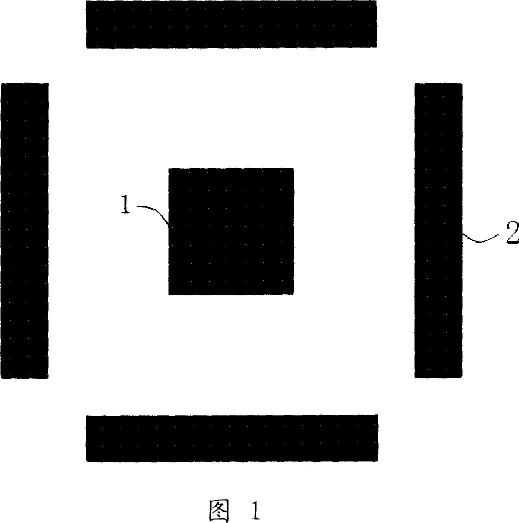
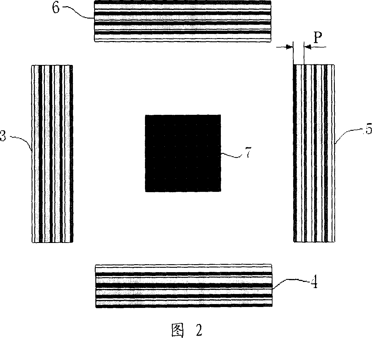
[0041] As shown in FIG. 2 , the test marks used in the present invention include a square inner mark 7 and four sets of outer marks 3 , 4 , 5 , 6 . The periods of the four groups of external marks 3, 4, 5, and 6 are the same, and the difference between two adjacent groups of external marks is 90°. In the figure, external mark 4 can be obtained by rotating external mark 3 clockwise by 90°; external mark 5 can be obtained by rotating external mark 4 clockwise by 90°; external mark 6 can be obtained by rotating...


PUM


Abstract

The related testing mark for projection objective image difference of photo-etching machine comprises a square inner mark and four external group marks around the inner one. Wherein, every external group of marks includes at least two lines with different width to periodical close arrange and form the marks; and the periods of all four groups are same. This invention simplifies the process and algorithm, and can achieve high testing precision.

Description

technical field [0001] The invention relates to a technology for detecting the quality of an object image projected by a lithography machine, in particular to a test mark used for detecting the image difference of an object projected by a lithography machine, a mask with the test mark, and a method for on-site detection of the image difference of an object projected by a lithography machine. Background technique [0002] The aberration of the projection objective lens is an important factor affecting the imaging quality of the projection lithography machine. With the continuous reduction of lithographic feature size, the impact of both low-order aberrations and high-order aberrations on imaging quality has become more and more prominent, and aberration detection technology has also become an important means to ensure lithography performance. Therefore, high-precision aberration on-site measurement technology is indispensable. [0003] DAMIS (Displacements At Multiple Illumi...

Claims


Application Information

Patent Timeline
Patent Type & Authority Applications(China)
IPC IPC(8): G03F7/20G03F1/00H01L21/027G03F1/44
Inventor 马明英王向朝王帆
Owner SHANGHAI MICRO ELECTRONICS EQUIP (GRP) CO LTD
Why Eureka
Try Eureka