

Front end module
A front-end module and input terminal technology, which is applied in the field of front-end modules, can solve the problems of degrading the performance of the receiving unit, making it difficult to minimize mobile communication equipment, and mixing phase noise.
- Summary
- Abstract
- Description
- Claims
- Application Information
AI Technical Summary
Problems solved by technology
Method used
Image

Examples
no. 1 example
[0075] The FEM according to the first embodiment of the present invention will now be briefly described.
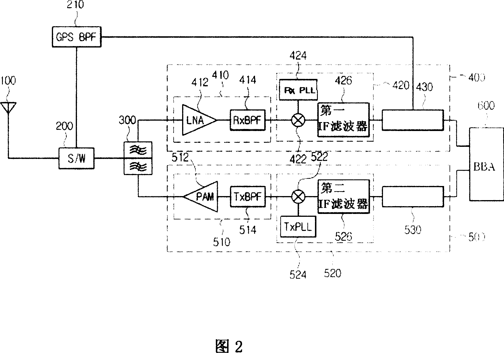
[0076] FIG. 2 is a block circuit diagram of a FEM according to a first embodiment of the present invention.
[0077] Referring to FIG. 2 , the FEM according to the first embodiment of the present invention includes: a duplexer 300 , a receiver 400 and a transmitter 500 . The receiver 400 includes: a radio frequency (RF) receiving unit 410, the radio frequency (RF) receiving unit 410 has a low noise amplifier (LNA) 412 and a receiving bandpass filter (RxBPF) 414; an intermediate frequency (IF) receiving unit 420, the intermediate frequency The (IF) receiving unit 420 has a first mixer 422 and a first phase-locked loop circuit 424 and a first IF filter 426 ; and a reception processing unit 430 .
[0078] The transmitter 500 includes: an RF transmit unit 510 having a PAM 512 and a transmit bandpass filter (Tx BPF) 514; an IF transmit unit 520 having a second mixer 522 and a...
no. 2 example
[0112] Fig. 5 is a block circuit diagram of a FEM according to a second embodiment of the present invention.
[0113] Referring to FIG. 5 , the FEM according to the first embodiment of the present invention includes: a duplexer 300 , a receiver 400 and a transmitter 500 . The FEM of the second embodiment is similar to the first embodiment.
[0114] Compared with the first embodiment of the present invention, the second embodiment of the present invention further comprises: an inductor 110 connected to the antenna terminal of the duplexer 300 , and a load switch 220 connected to the PAM 512 .
[0115] Referring to FIG. 5 , load switch 220 acts as an amplifier for turning on or off PAM 512 .
[0116] The load switch 220 may be configured as a discrete switching device, or may be configured as a switching circuit having a resistor, a switching transistor, a capacitor and a diode.
[0117] The load switch 200 receives the control signal of the baseband processing unit 600, and t...
no. 3 example
[0166] A FEM according to a third embodiment of the present invention will now be described. The FEM according to the third embodiment of the present invention is a communication module having a diversity receiving unit, which is installed in a mobile communication device, and handles communication using the CDMA 1xEV-DO standard.
[0167] Fig. 17 is a schematic block diagram of a FEM according to a third embodiment of the present invention.
[0168] Referring to FIG. 17, the FEM 190 according to the third embodiment of the present invention includes: a duplexer 105, a PAM 111, a transmit filter 115, a transmit processing unit 130, a first receive filter 120, a second receive filter 121, a first The receiving processing unit 140 , the second receiving processing unit 150 and the GPS filter 125 . These components are manufactured as discrete components and mounted in MCMs.
[0169] The MCM mounting structure will be described later with reference to FIG. 18 .
[0170] The du...
PUM
 Abstract
Description
Claims
Application Information