

Endoscope insertion auxiliary device
An auxiliary device and endoscope technology, which is applied to endoscopes, telescopes, medical science, etc., can solve the problems of complex structure, insufficient contact, and inability to insert with ordinary endoscopes.
- Summary
- Abstract
- Description
- Claims
- Application Information
AI Technical Summary
Problems solved by technology
Method used
Image

Examples
Embodiment 1
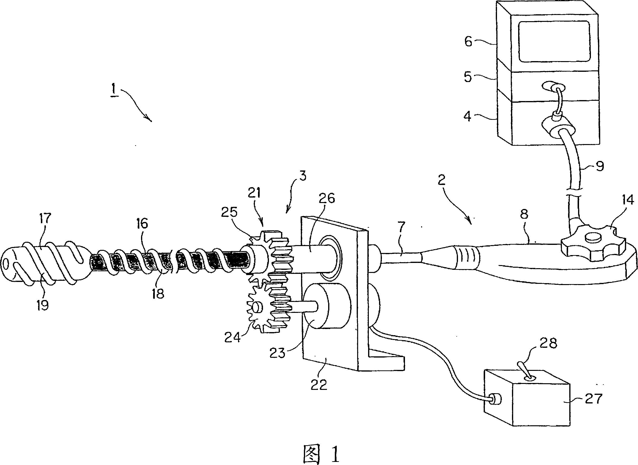
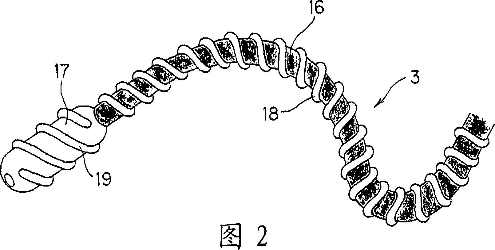
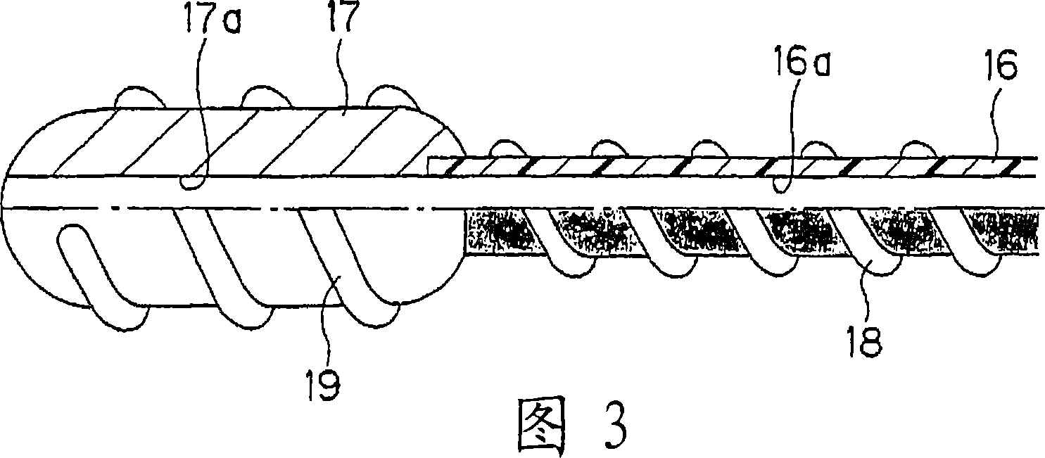
[0156] Embodiment 1 of the present invention will be described with reference to FIGS. 1 to 16 .
[0157] As shown in FIG. 1 , the endoscope apparatus 1 provided with Embodiment 1 has: an endoscope 2 for performing endoscopic examination, etc.; The endoscope insertion assisting device 3 of Example 1; the light source device 4 for supplying illumination light to the endoscope 2; the camera control unit (abbreviated as CCU) 5 for performing signal processing for the imaging element built in the endoscope 2; And the monitor 6, which receives the video signal output from the CCU 5, displays the endoscopic image captured by the imaging element.
[0158]The endoscope 2 has a flexible and elongated insertion portion 7 inserted into a body cavity or the like; an operation portion 8 provided at the rear end of the insertion portion 7 ; and a cable portion 9 extending from the side of the operation portion 8 . Here, the end of the cable portion 9 is connected to the light source device...
Embodiment 2
[0206] Next, Embodiment 2 of the present invention will be described.
[0207] FIG. 17 schematically shows an endoscope insertion assisting device 3H according to Embodiment 2 of the present invention. In this endoscope insertion assisting device 3H, for example, a rotation drive device 60 is provided on the rear end side of the tube 16 .
[0208] The rotation driving device 60 has a gear 61a attached to the rear end of the pipe 16, and a gear 61b meshing with the gear 61a and connected to a motor 63 via a torque limiter 62 serving as rotation limiting means.
[0209] Furthermore, the spiral structure 18 provided on the outer peripheral surface of the tube 16 is constituted by a hollow tube. The front end of the hollow tube is closed, and the rear end is connected to a compressor 64 .
[0210] Furthermore, the motor 63 and the compressor 64 are connected to a control unit 65 , and the control unit 65 is connected to an operation unit 66 . By operating the operation unit 66 ...
Embodiment 3
[0273] Next, Embodiment 3 of the present invention will be described. Fig. 35 schematically shows an endoscope insertion assisting device 3L according to a third embodiment of the present invention. The endoscope insertion assisting device 3L is attached to the outer peripheral surface of the endoscope 2 for assisting insertion.
[0274]In the endoscope insertion assisting devices 3 to 3K described in Embodiments 1 and 2, a hollow portion for inserting the insertion portion 7 of the endoscope 2 is provided, but the insertion portion 7 that can be inserted into the hollow portion is formed for the thin diameter. In this way, observation is actually possible, but sometimes it is limited to an endoscope that does not have a channel for inserting a treatment tool, and in this case, treatment cannot be performed.
[0275] Therefore, this embodiment can also be applied to the endoscope 2 having the channel 91 through which the treatment instrument can be inserted.
[0276] Theref...
PUM
 Abstract
Description
Claims
Application Information