Laser cutting method and apparatus

A technology of cutting device and cutting method, which is applied in the direction of welding equipment, laser welding equipment, metal processing equipment, etc., can solve problems such as inappropriateness, and achieve the effects of saving man-hours, improving production efficiency, and saving return time

Inactive Publication Date: 2007-04-04
FOXSEMICON INTEGRATED TECHNOLOGY (SHANGHAI) INC +1
View PDF0 Cites 14 Cited by
  • Summary
  • Abstract
  • Description
  • Claims
  • Application Information

AI Technical Summary

Problems solved by technology

This is not suitable for efficient panel cutting

Method used


Image

  • Laser cutting method and apparatus
  • Laser cutting method and apparatus
  • Laser cutting method and apparatus

Examples


Embodiment Construction

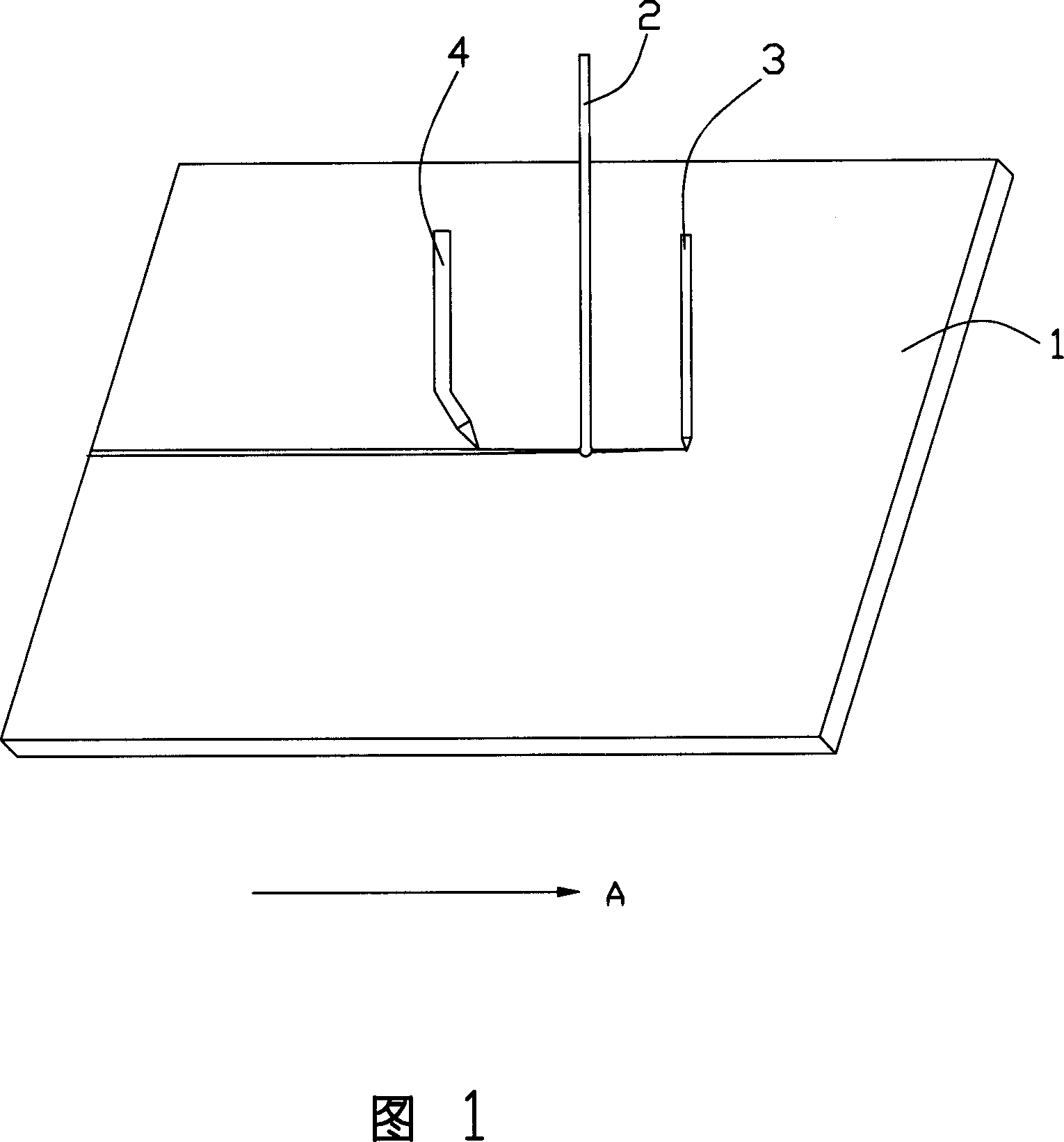
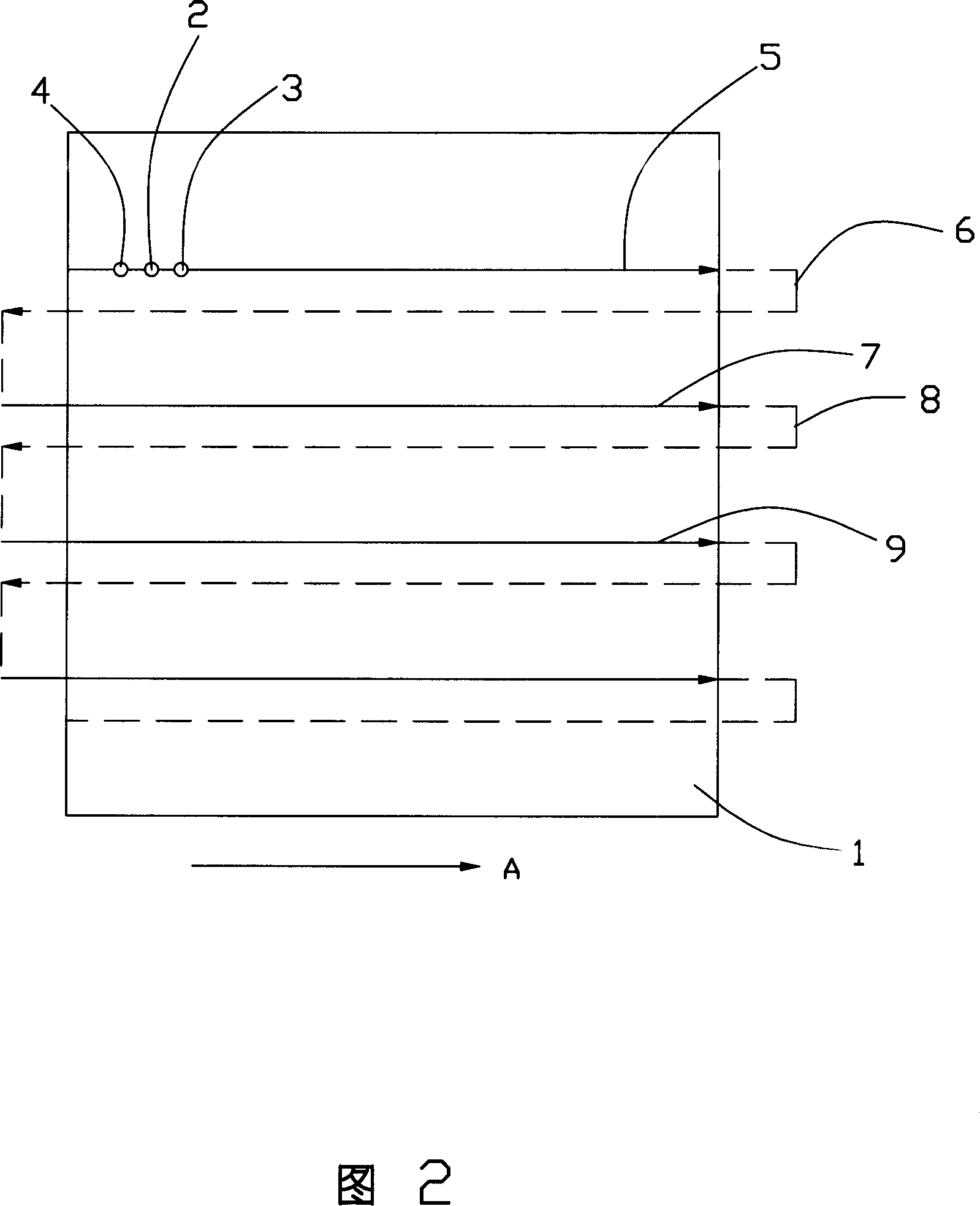
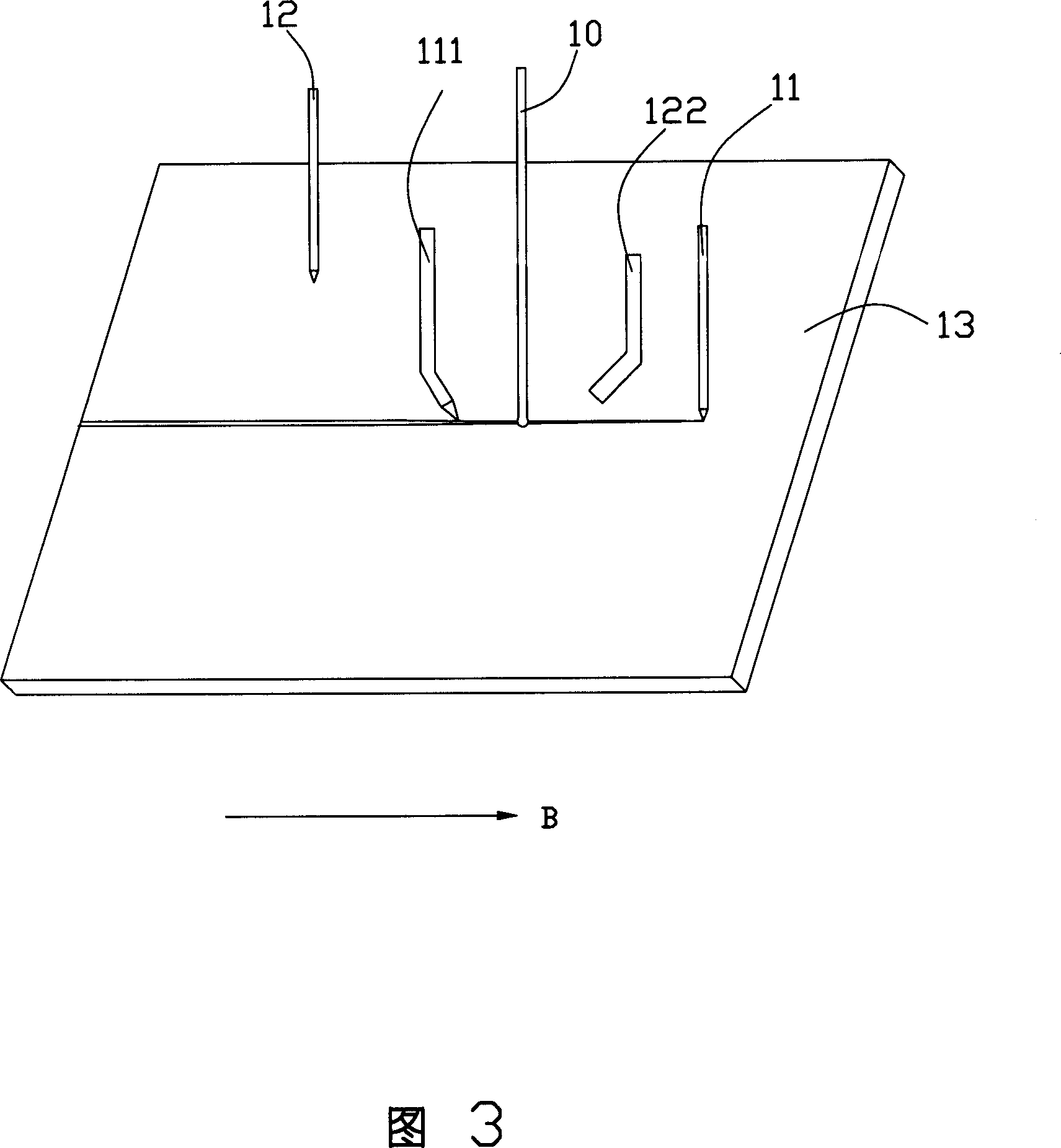
[0020] Referring to FIGS. 3 to 5, the laser cutting unit for cutting glass substrate 13 of the present invention includes a laser system 10, a first marking tool 11, a first cooling system 111, a second marking tool 12 and a second marking tool 12. cooling system 122 .

[0021] In the laser cutting unit of the present invention, the first scribing tool 11 and the second scribing tool 12 can be any tools that can generate predetermined cracks on the surface of the glass substrate, such as laser beams, diamond knives, and cutter wheels. The first cooling system 111 and the second cooling system 122 can be a single liquid, a mixture of a single gas and a single liquid, or a mixture of more than one gas and liquid, such as pure water, cooling oil, liquid nitrogen or liquid helium.

[0022] Compared with the existing laser cutting technology, the laser system 10 of the laser cutting unit of the present invention, the marking tool 11,12 and the cooling system 111,122 do not involve ...


PUM


Abstract

A laser cutting machine for cutting the brittle material is composed of a laser system, the first cutting system consisting of the first cooling unit and the first ruling unit, and the second cutting system consisting of the second cooling unit and the second ruling unit. Its cutting method includes such steps as cutting by said laser system and the first cutting system along the first direction, cutting by said laser system and the second cutting system along reverse direction, and so on.

Description

【Technical field】 [0001] The invention discloses a laser cutting device and a cutting method thereof, in particular to a laser cutting device for cutting brittle materials such as liquid crystal display (TFT-LCD) (Thin Film Transistor, referred to as TFT; LiquidCrystal Display, referred to as LCD) glass panel Laser cutting device and cutting method thereof. 【Background technique】 [0002] With the continuous development of technology, liquid crystal display devices (TFT-LCD) have been widely used in the consumer field due to their own characteristics. It is regarded as a strong opponent to replace the traditional cathode ray tube (Cathode Ray Tube, CRT for short) display device. [0003] A liquid crystal display device is generally composed of two glass substrates, liquid crystal contained in the two glass substrates and a number of circuits. The liquid crystal can change the arrangement mode under the influence of the electric field to complete the display operation. In ...

Claims


Application Information

Patent Timeline
Patent Type & Authority Applications(China)
IPC IPC(8): B23K26/00B23K26/42B25H7/04B23K26/38B23K26/70
Inventor 傅承祖黄俊凯陈献堂郑凯仁张定宏
Owner FOXSEMICON INTEGRATED TECHNOLOGY (SHANGHAI) INC
Why Eureka
Try Eureka