Centrifugal switch driver for single-phase inductive motor

A single-phase induction motor and centrifugal switch technology, applied in the direction of electric switches, circuits, electrical components, etc., can solve the problems of centrifugal weight noise, spring breakage, longer assembly time, etc.

Inactive Publication Date: 2007-04-04
LG ELECTRONICS (TIANJIN) APPLIANCES CO LTD
View PDF0 Cites 2 Cited by
  • Summary
  • Abstract
  • Description
  • Claims
  • Application Information

AI Technical Summary

Problems solved by technology

Due to the movement of the above-mentioned movable part collar, the process of operating the switch inside the casing after the movable control rod of the centrifugal switch is driven, and the centrifugal counterweight is in the state of being pulled by the spring after being opened to the radial direction due to the centrifugal force during operation, Once the motor is running, due to the elastic recovery force of the spring, the centrifugal weight will repeat the process of returning to the original position, and the following problems will occur: when it is used for a long time, the spring will break or the centrifugal weight will produce noise.
In addition, since the structure is complex and requires many parts, an additional process is required when assembling the entire movable part, resulting in a long assembly time.

Method used


Image

  • Centrifugal switch driver for single-phase inductive motor
  • Centrifugal switch driver for single-phase inductive motor
  • Centrifugal switch driver for single-phase inductive motor

Examples


Embodiment Construction

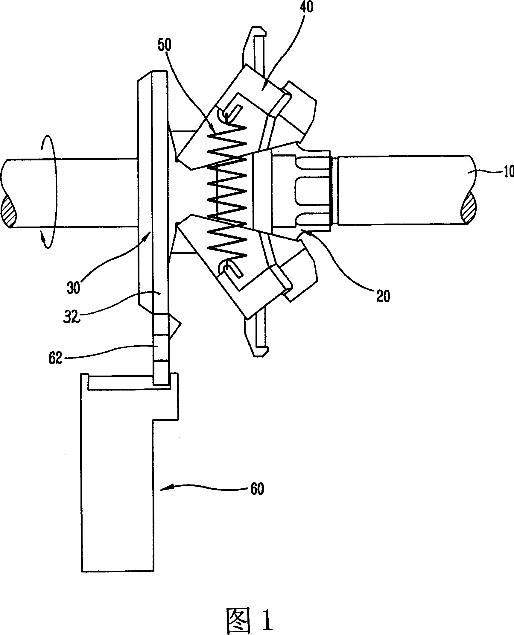
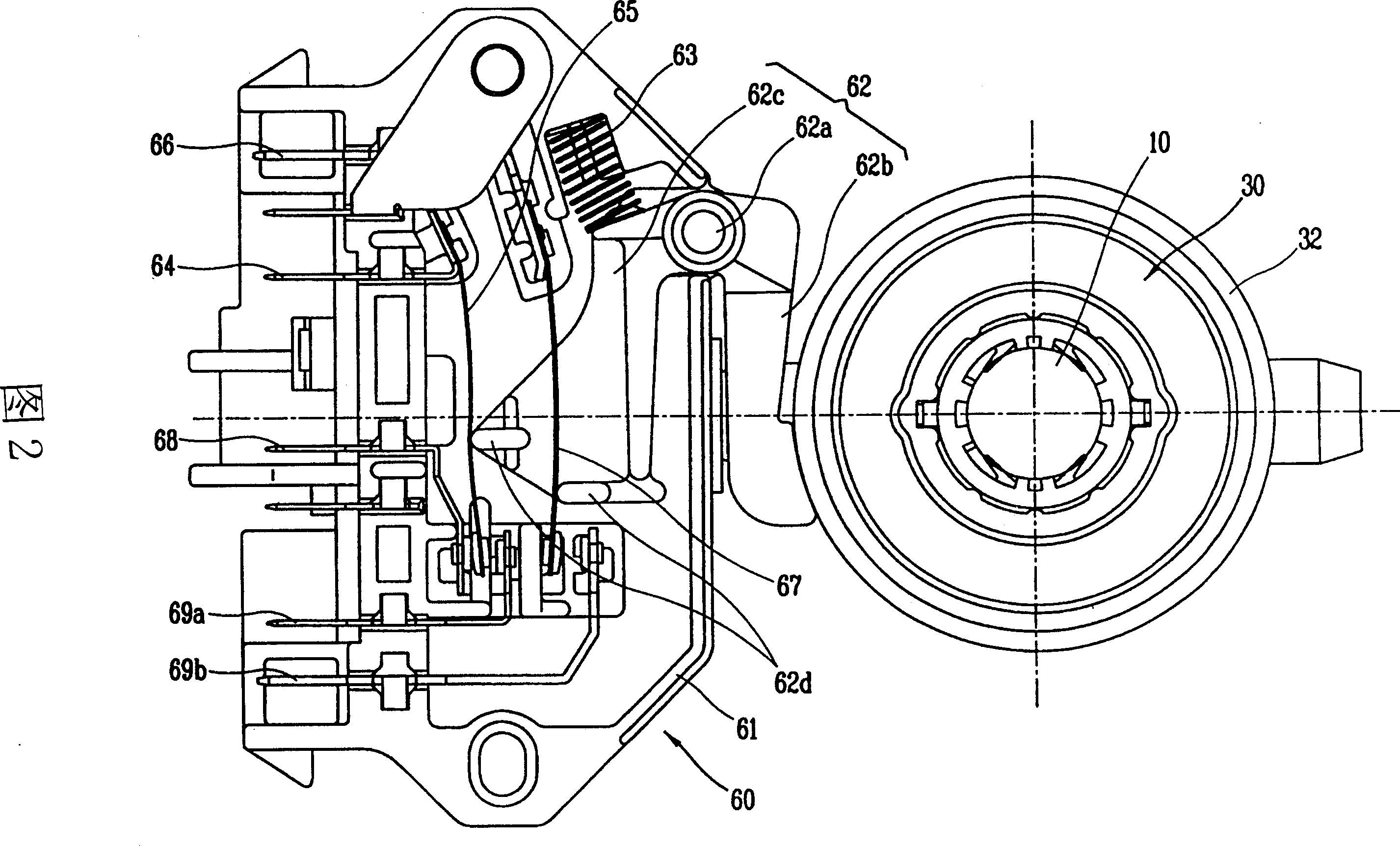
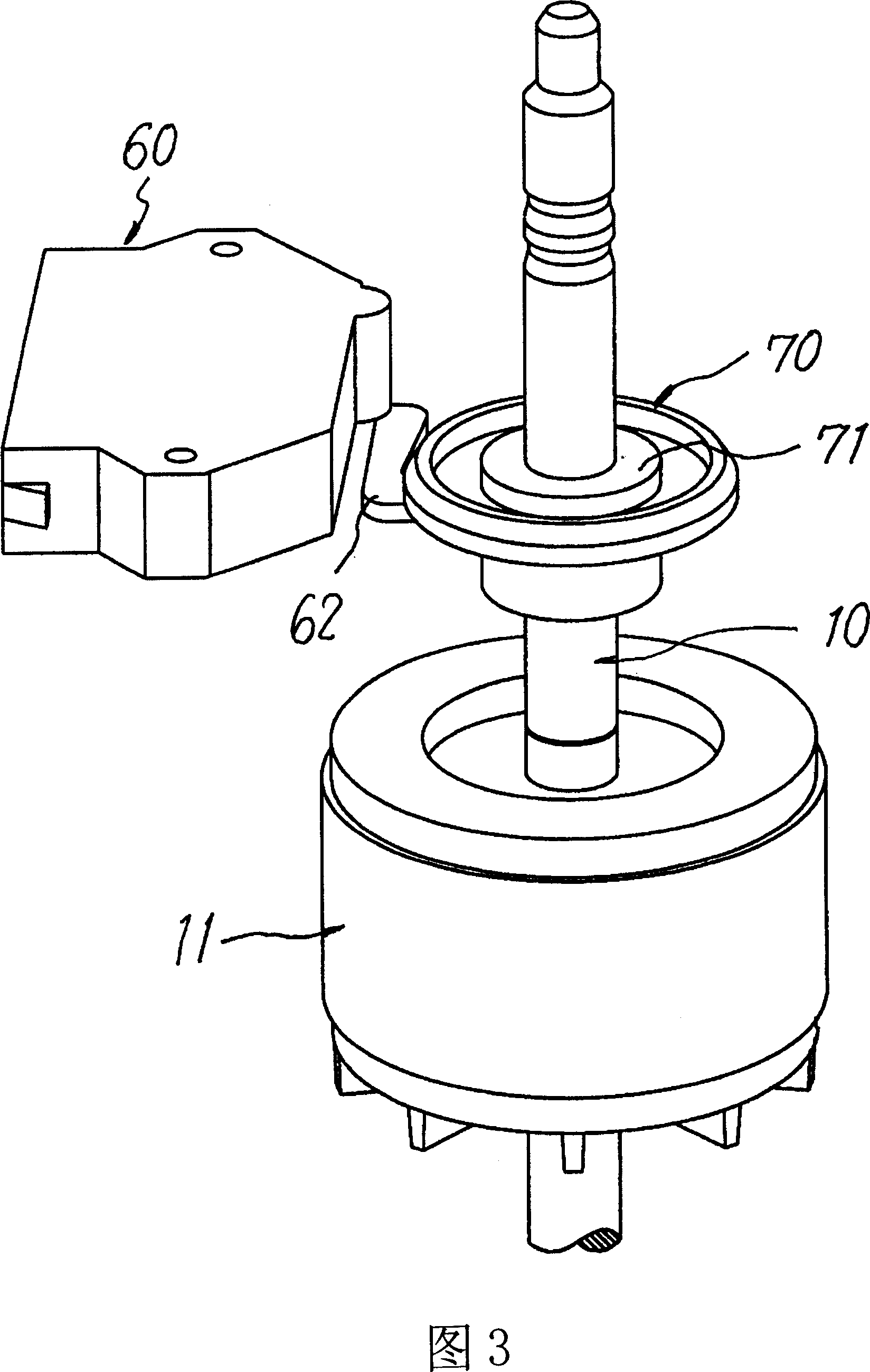
[0028] As shown in Figures 3 to 6, the present invention includes: a rotating shaft 10 combined with a rotor iron core 11 of a single-phase induction motor; a sliding wheel 70 that is rotatably lifted and combined with the above-mentioned rotating shaft 10 to drive a centrifugal switch 60; The sleeve 71 provided at the central portion of the above-mentioned sliding wheel 70 and the spiral groove 81 and the spiral convex groove 82 formed on the inner and outer diameter portions of the rotating shaft 10 constitute the above-mentioned sliding wheel 70 due to the rotation of the above-mentioned rotating shaft 10. The sliding pulley drive unit 80 that rotates up and down.

[0029] The spiral groove 81 of the spiral sliding wheel driving portion 80 is formed only up to the upper end of the spiral convex groove 82 shown in FIG. 4 , so the spiral convex groove 82 can only move to this part.

[0030] As mentioned above, in the single-phase induction motor centrifugal switch driving dev...


PUM


Abstract

The invention is concerned with the centrifugal switch driving equipment for the single-phase induction machine, includes: the rotating axis of the single-phase induction machine; the slipping wheel that is rotary and fluctuant combines with the rotating axis and the centrifugal switch driving equipment; the slipping wheel driving part that is set at the central sleeve 71 of the slipping wheel and formed at the spiral groove and the spiral protruding groove of the rotating axis inner and outer diameter, which makes the slipping wheel to rotate and fluctuate by the rotation of the rotating axis.

Description

technical field [0001] The invention relates to a centrifugal switch driving device for a single-phase induction motor. Background technique [0002] Generally speaking, an electric motor is a device that converts electrical energy into mechanical energy. And according to the different power supply, it can be divided into DC motor and AC motor. AC motors are divided into induction motors, synchronous motors and commutator motors. Induction motors are divided into three-phase induction motors and single-phase induction motors. [0003] Single-phase induction motors are widely used in driving motors for household, office, industrial, and agricultural appliances because of their simple and firm structure, and single-phase power supply is relatively easy to obtain. The above-mentioned single-phase induction motor cannot start by itself, so in order to generate starting force, a sub-coil having a phase difference from the main coil is provided in addition to the main coil. Ge...

Claims


Application Information

Patent Timeline
Patent Type & Authority Applications(China)
IPC IPC(8): H01H35/10H02P1/12
Inventor 李善重
Owner LG ELECTRONICS (TIANJIN) APPLIANCES CO LTD
Why Eureka
Try Eureka