Sealed electric-motor and sealed pump

A technology of electric motors and sealed pumps, which is applied in the direction of electric components, machines/engines, liquid fuel engines, etc., can solve the problems of installation error, torque performance difference, increase assembly adjustment process, motor performance degradation, etc., and achieve stable output performance , The installation error is small, the effect of improving the accuracy

Inactive Publication Date: 2007-04-04
SANKYO SEIKI MFG CO LTD
View PDF1 Cites 19 Cited by
  • Summary
  • Abstract
  • Description
  • Claims
  • Application Information

AI Technical Summary

Problems solved by technology

In particular, if the positional relationship between the stator 10 and the magnetic sensor 20 deviates from the design value, the performance of the motor will be greatly reduced, and the efficiency of the pump will deteriorate.
[0008] In the hermetic pump described in the conventional patent document 1, the magnetic sensor 20 is mounted on the substrate of the control unit 12, so the installation error between the control unit 12 and the stator 10, the installation error between the control unit 12 and the magnetic sensor 20, The inclination errors of the mounted magnetic sensor 20 add up, deteriorating the performance of the motor, and causing a problem in which the specified pump performance cannot be obtained.
In additio

Method used


Image

  • Sealed electric-motor and sealed pump
  • Sealed electric-motor and sealed pump
  • Sealed electric-motor and sealed pump

Examples


Embodiment Construction

[0040] Hereinafter, the hermetic motor and hermetic pump of the present invention will be described with reference to the drawings.

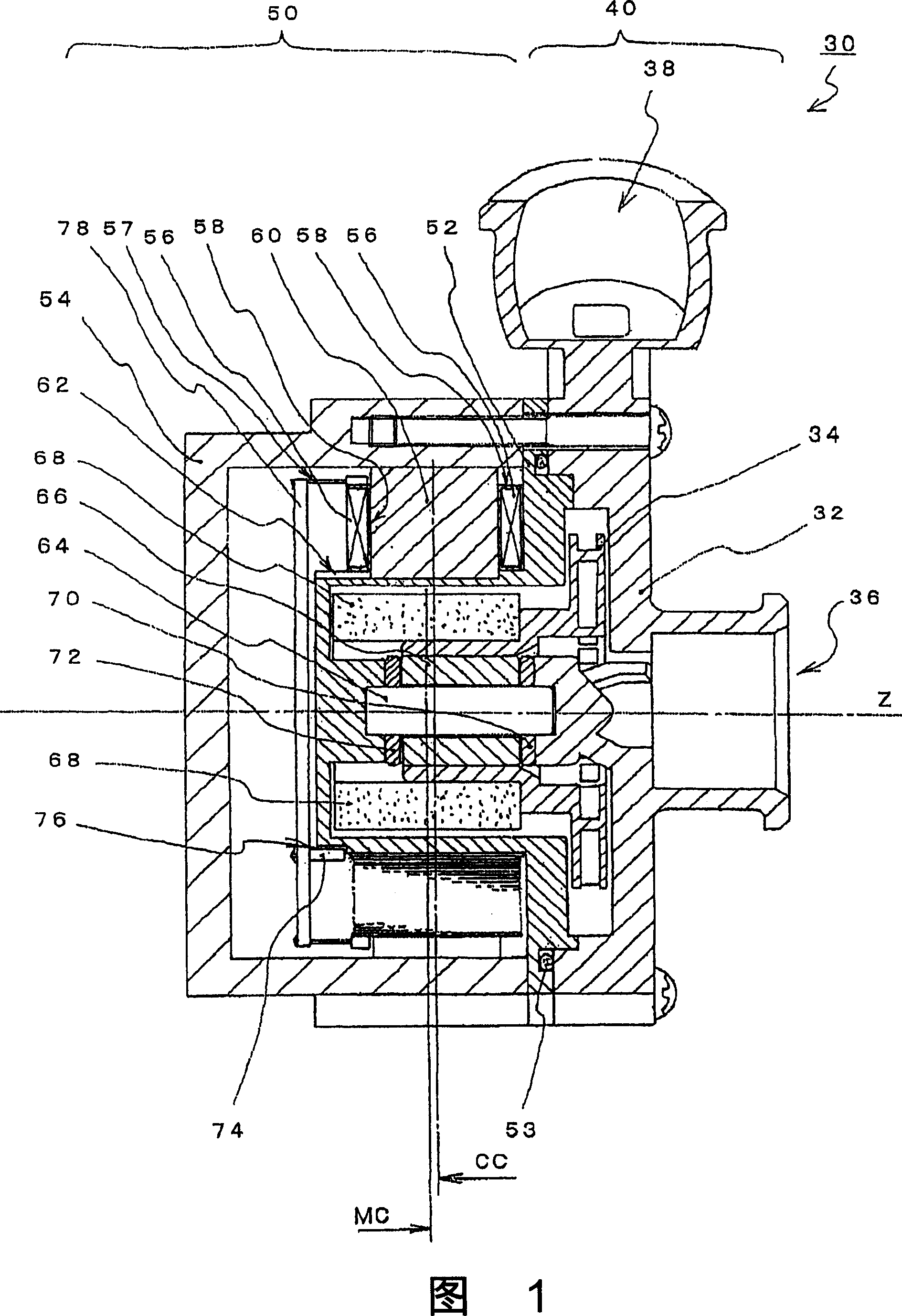
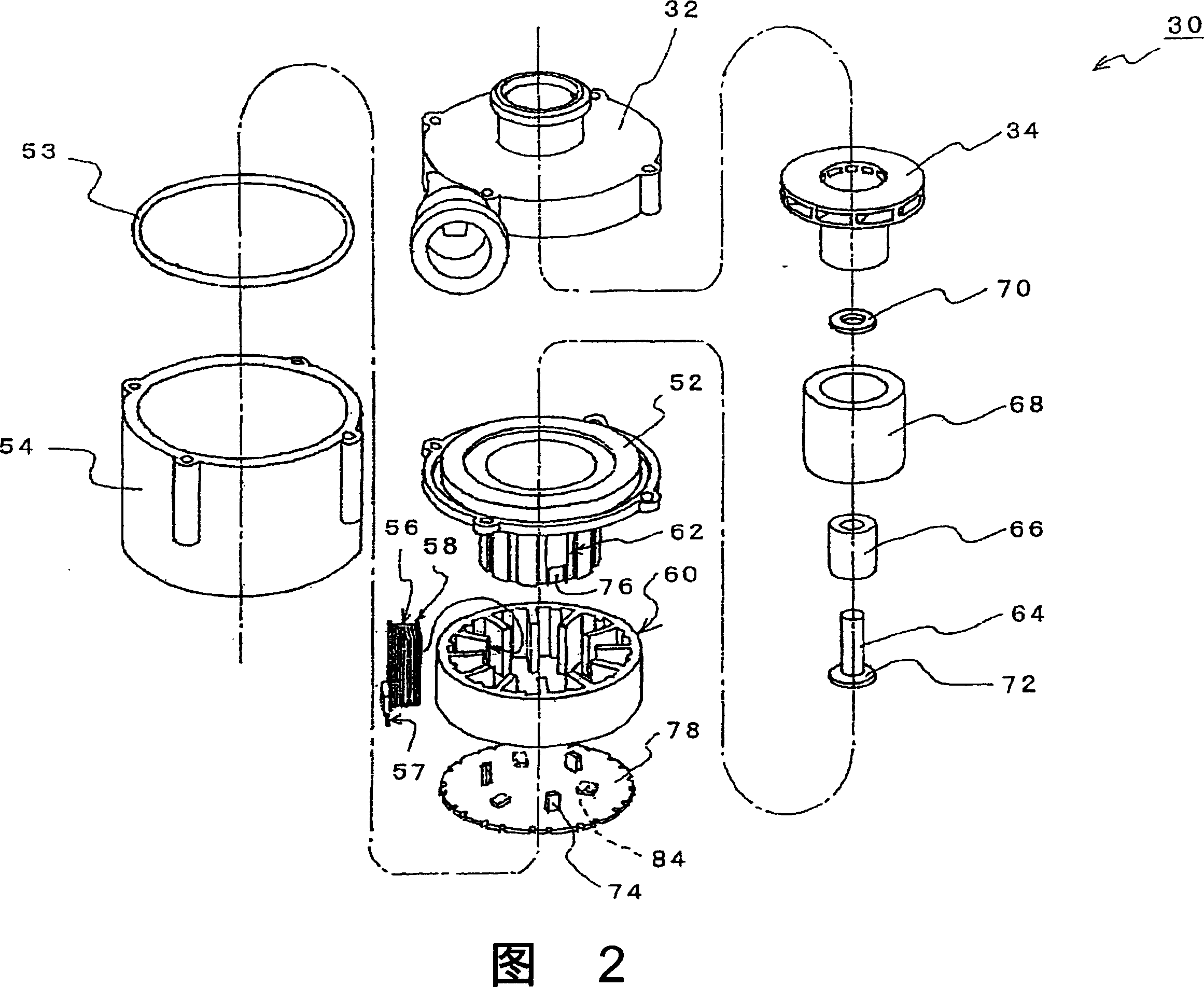
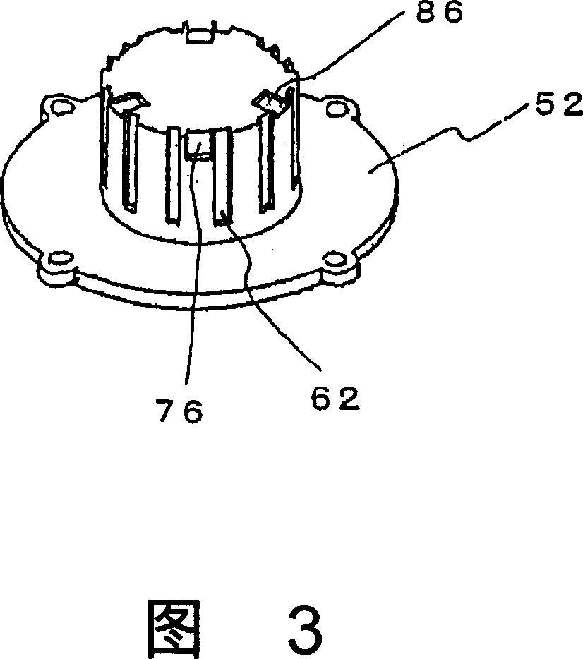
[0041] FIG. 1 is a cross-sectional view showing an example of a hermetic pump 30 using a hermetic motor 50 according to the present invention. The upper half above the center line Z in FIG. 1 is a section where the stator core 60 is located, and the lower half below the center line Z in FIG. 1 is a section where the magnetic sensor 74 is located. In addition, FIG. 2 is a perspective view showing a state in which the sealed pump 30 shown in FIG. 1 is disassembled into parts. FIG. 3 is a perspective view of the can body 52 viewed from the bottom side.

[0042] As shown in Figures 1 and 2, the sealed pump 30 of the present invention includes a sealed motor 50 and a pump portion 40, wherein the sealed motor 50 has a stator core 60, a rotor magnet 68 and a tank body 52, and the tank body 52 combines the stator iron The core 60 is sealed away from t...


PUM


Abstract

The present invention provides an inexpensive canned motor which is efficient as a motor and is little in dispersion of performance. In this canned motor (50) which has a can (52) for isolating and sealing the stator core (60) of a DC brushless motor from a rotor magnet (68), the can (52) has a core positioning part (62) which positions the stator core (60) in the rotational direction of the rotor magnet (68) and a sensor positioning part (76) which positions the magnetic sensor (74) for detecting the magnetic pole of the rotor magnet (68), in the rotational direction of the rotor magnet (68). It is to be desired that the above core positioning part (62) should be recessed. Moreover, it is to be desired that the above sensor positioning part (76) should be recessed in parallel with the rotating shaft of the rotor magnet (68), or recessed in parallel with a sensor board for mounting a magnetic sensor (74).

Description

technical field [0001] The present invention relates to a hermetic motor and a hermetic pump, and more particularly, to a hermetic motor and hermetic pump having a tank that seals a stator core of a DC brushless motor away from a rotor magnet. Background technique [0002] As a pump that pressurizes and discharges fluid for supplying hot water or water, there is known a hermetic pump in which the rotor magnet and the impeller of the motor are housed in the pump chamber in an integrated structure, and are shielded by the fluid The stator core of the motor is arranged at the position of the partition wall (tank body). Conventionally, such sealed pumps generally use an AC motor with a simple structure, but a sealed pump using a DC motor is being developed in response to a demand for power saving (for example, Patent Document 1). [0003] FIG. 4 is a cross-sectional view of the hermetic pump shown in Patent Document 1. FIG. The sealed pump shown in Fig. 4 comprises: the rotor ...

Claims


Application Information

Patent Timeline
IPC IPC(8): H02K29/06F04D13/06F04D29/42
CPCF04D13/0626F04D13/0606H02K11/0021F04D13/064H02K5/128H02K11/215
Inventor 小泽健
Owner SANKYO SEIKI MFG CO LTD
Why Eureka
Try Eureka