
Automatic control method for color enlarging machine head

A technology of color expansion machine head and automatic control device, which is applied to the camera, camera body, optics, etc., can solve the problems of inability to hold the precision, inconvenient, etc., and achieve the effect of accurate adjustment and prevention of misoperation

Inactive Publication Date: 2007-04-11
SHANG HAI DOLI PHOTOGRAPHIC EQUIP
View PDF0 Cites 1 Cited by
  • Summary
  • Abstract
  • Description
  • Claims
  • Application Information

AI Technical Summary

Problems solved by technology

In the past, manual adjustment was used, which was extremely inconvenient and the accuracy could not be supported.

Method used


Image

  • Automatic control method for color enlarging machine head

Examples


Embodiment Construction

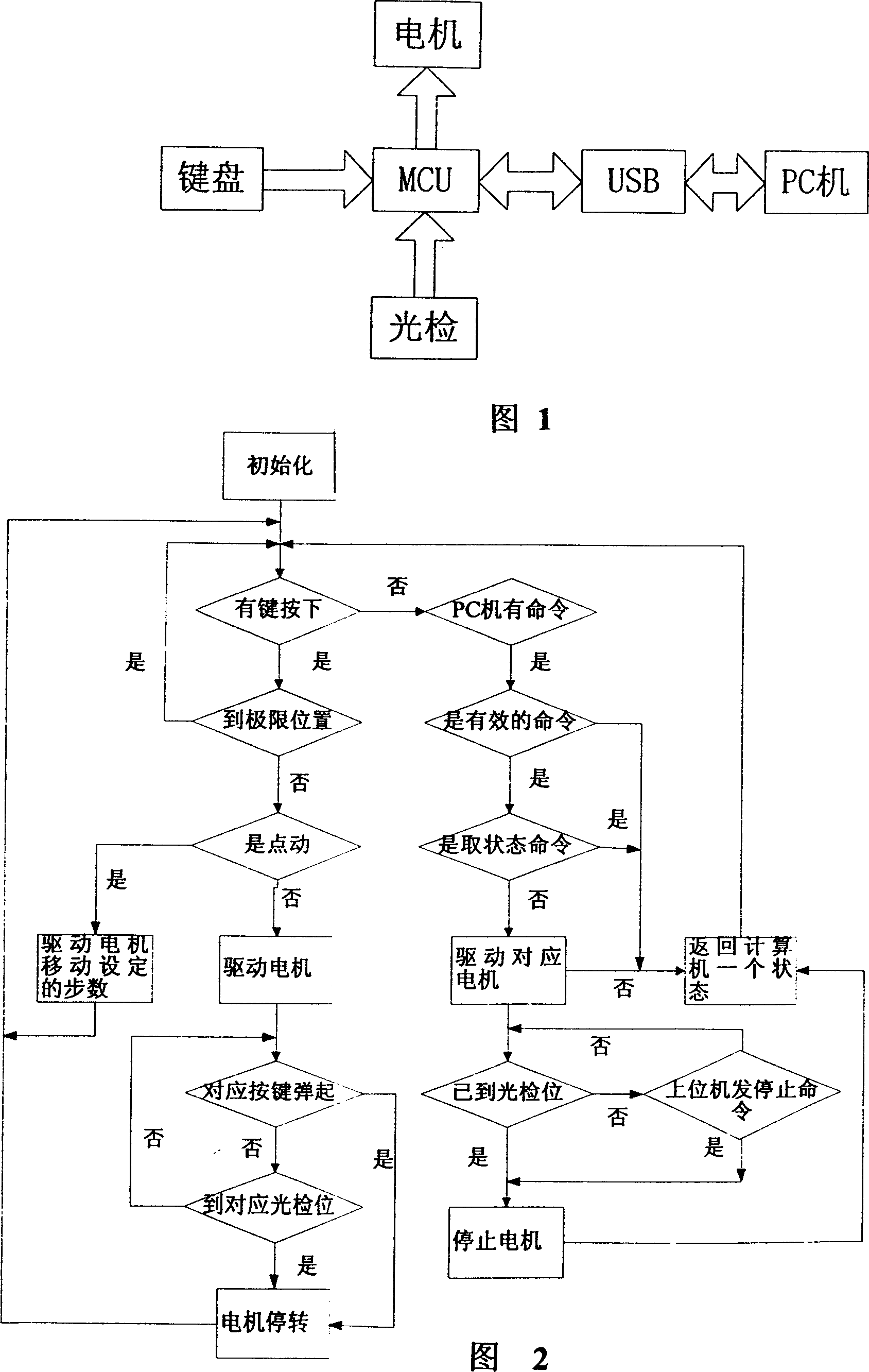
[0032] Microcontroller (MCU) of the present invention adopts chip C8051F022, 3.3V single power supply support, 64K FLASH program space; And the 3.3V characteristic itself of MCU itself also provides convenience for simplifying power supply design; This MCU has 10bitA / D ( Analog-to-digital) conversion, with 2.4V (reference voltage) Ref, which makes the peripheral design quite convenient, so it provides convenience for saving board space; it also supports ISP (system programmable). The USB driver chip is CH375S. Through this chip, PC can control the system.

[0033] The device used in light detection is a pair of emitting and receiving diodes. Under normal circumstances, the receiving diode can receive the light wave emitted from the emitting diode. When the shield covers the emitting diode, the receiving diode cannot receive light waves. Using this feature, put the light detector at the limit position of the pan-tilt movement, and the MCU can control the limit position of th...


PUM


Abstract

To control the console shift of Minilab automatically, this invention uses the method of button plus USB control, in which, users can use the button to control the action of console, or use PC to give off the control order and send to the circuit board through USB to control the console. The console has six directions and three degrees of freedom, which can move forward, backward, downward, upward, and rotate on the left and right. The invention totally uses six buttons to control six directions, and one button controls one direction. When users press the button, the console will move in the corresponding direction of the button, and when users loose the button, it will stop. In addition, users can also use the way of dot action, which is to loose the button immediately after pressing, and the console will move in a small angle in this direction, which plays as fine-tuning, so that users can conduct it. In addition, users can use PC to control console through USB, and set the step number for precise control.

Description

Technical field: [0001] The invention relates to a device and method for controlling the displacement of a pan-tilt of a color expansion machine. Background technique: [0002] The gimbal is an adjustable bracket that supports the camera. When taking ID photos, the height and angle of the camera need to be adjusted each time because the height, weight, and sitting position of the subject being photographed are different. In the past, manual adjustment was used, which was extremely inconvenient and the accuracy could not be supported. Invention content: [0003] In order to achieve the purpose of automatically controlling the displacement of the pan-tilt, the present invention adopts the method of button plus USB control, the user can use the button to control the movement of the pan-tilt or issue a control command through the PC, and then transmit it to the circuit board through the USB. Control the movement of the gimbal. [0004] The present invention arranges a micro-...

Claims


Application Information

Patent Timeline
Patent Type & Authority Applications(China)
IPC IPC(8): G03B17/56G03B27/32G03B27/52G03B27/72
Inventor 张建国孙健
Owner SHANG HAI DOLI PHOTOGRAPHIC EQUIP
Learn More