Micro strip antenna

A technology of microstrip antenna and microstrip line, which is applied in the field of communication, can solve the problems of increasing high-frequency loss, destroying circuit system matching, and deteriorating antenna directivity, so as to reduce high-frequency loss and suppress high-order harmonics Effect

Inactive Publication Date: 2007-04-11
ZHEJIANG UNIV
View PDF0 Cites 9 Cited by
  • Summary
  • Abstract
  • Description
  • Claims
  • Application Information

AI Technical Summary

Problems solved by technology

The traditional way to achieve the above requirements is to improve the integration of the system, but in addition to the fundamental wave, the antenna will generate high-order harmonics in the process of receiving / transmitting signals, which will worsen the electromagnetic interference (EMI) problem of the internal components of the system
In order to suppress the interference of high-order harmonics, a filter is usually added between the antenna and other components of the circuit such as amplifiers, but the result of this is to increase the cost of the circuit, increase the volume capacity of the entire circuit, and because it must be in Adding more connectors between the antenna and the filter and the amplifier further increases the circuit size, destroys the matching of the circuit system and increases high-frequency loss
Moreover, due to the influence of the external filter, the function of the original antenna system is often adversely affected, such as the directivity of the antenna is deteriorated.

Method used


Image

  • Micro strip antenna
  • Micro strip antenna
  • Micro strip antenna

Examples


Embodiment Construction

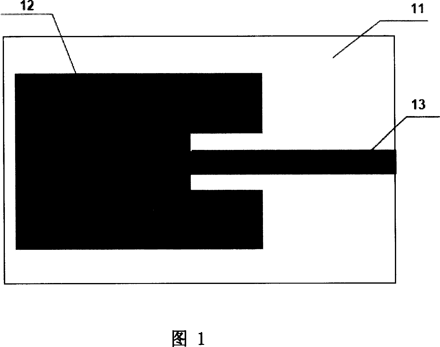
[0018] Refer to the structure of the existing patch antenna unit shown in FIG. 1 . The antenna includes a dielectric substrate 11, which is made of a material with a relatively high permittivity, such as a material with a relative permittivity of 10.2. A metal layer is attached to one side of the dielectric substrate 11 as a ground, and a concave metal sheet 12 is attached to the other side as a patch antenna unit. The microstrip feeder 13 is connected to the notch of the metal sheet.

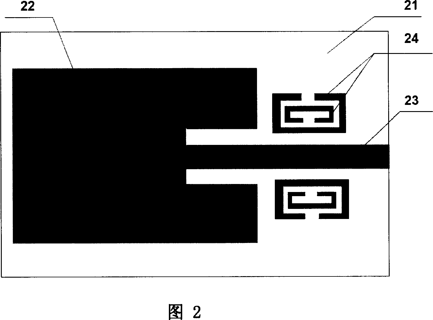
[0019] Fig. 2 is a structure of an antenna unit of an embodiment of the present invention. The antenna includes a dielectric substrate 21, which is made of a material with a relatively high permittivity, such as a material with a relative permittivity of 10.2. A metal layer is attached to one side of the dielectric substrate 21 as a ground, and a concave metal sheet 22 is attached to the other side as a patch antenna unit. The microstrip feeder 23 is connected to the notch of the metal sheet...


PUM


Abstract

This invention relates to an antenna working at the microwave band including a medium substrate, one side of which is adhered with a metal layer as the ground, the other side is adhered with a concave metal plate as a plate stick antenna unit and a micro-strip line as the feeding line connecting to the concave of the metal plate, and an artificial magnetic medium material is set symmetrically at both sides of the micro-strip line and adhered on the substrate. This invention can realize forbidden band at a certain working frequency sphere so as to suppress high order harmonics.

Description

technical field [0001] The invention belongs to the technical field of communication, and in particular relates to an antenna working in a microwave frequency band. By loading a new type of artificial electromagnetic medium material at both ends of a feeder line, common harmonic interference under high frequency conditions is suppressed. Background technique [0002] The development of modern wireless communication technology requires the transceiver terminal to make the whole system more compact and low-cost under the premise of keeping the performance of the whole system unchanged. The traditional way to achieve the above requirements is to improve the integration of the system, but in addition to the fundamental wave, the antenna will generate high-order harmonics in the process of receiving / transmitting signals, which will worsen the electromagnetic interference (EMI) problem of the internal components of the system . In order to suppress the interference of high-order ...

Claims


Application Information

Patent Timeline
Patent Type & Authority Applications(China)
IPC IPC(8): H01Q13/08H01Q1/38
Inventor 丁婕琛何赛灵
Owner ZHEJIANG UNIV
Why Eureka
Try Eureka