Cooling system

A cooling system and cooler technology, applied in the cooling of the engine, the arrangement of the combination of cooling of the power plant, component optimization, etc., can solve the problems of hindering the flow of cold air, rising pressure loss, etc., and achieve the goal of improving cooling efficiency and rapid heating Effect

Inactive Publication Date: 2007-05-02
贝洱公司
View PDF5 Cites 7 Cited by
  • Summary
  • Abstract
  • Description
  • Claims
  • Application Information

AI Technical Summary

Problems solved by technology

At high speeds, the fan impedes the flow of cold air, so the pressure loss rises

Method used


Image

  • Cooling system
  • Cooling system
  • Cooling system

Examples


Embodiment Construction

[0035] The cooling system 1 described below is generally used in motor vehicles, such as passenger cars, trucks, buses, etc., which have, for example, an internal combustion engine as drive unit. The cooling system can also be adapted without problems for electric or hybrid vehicles.

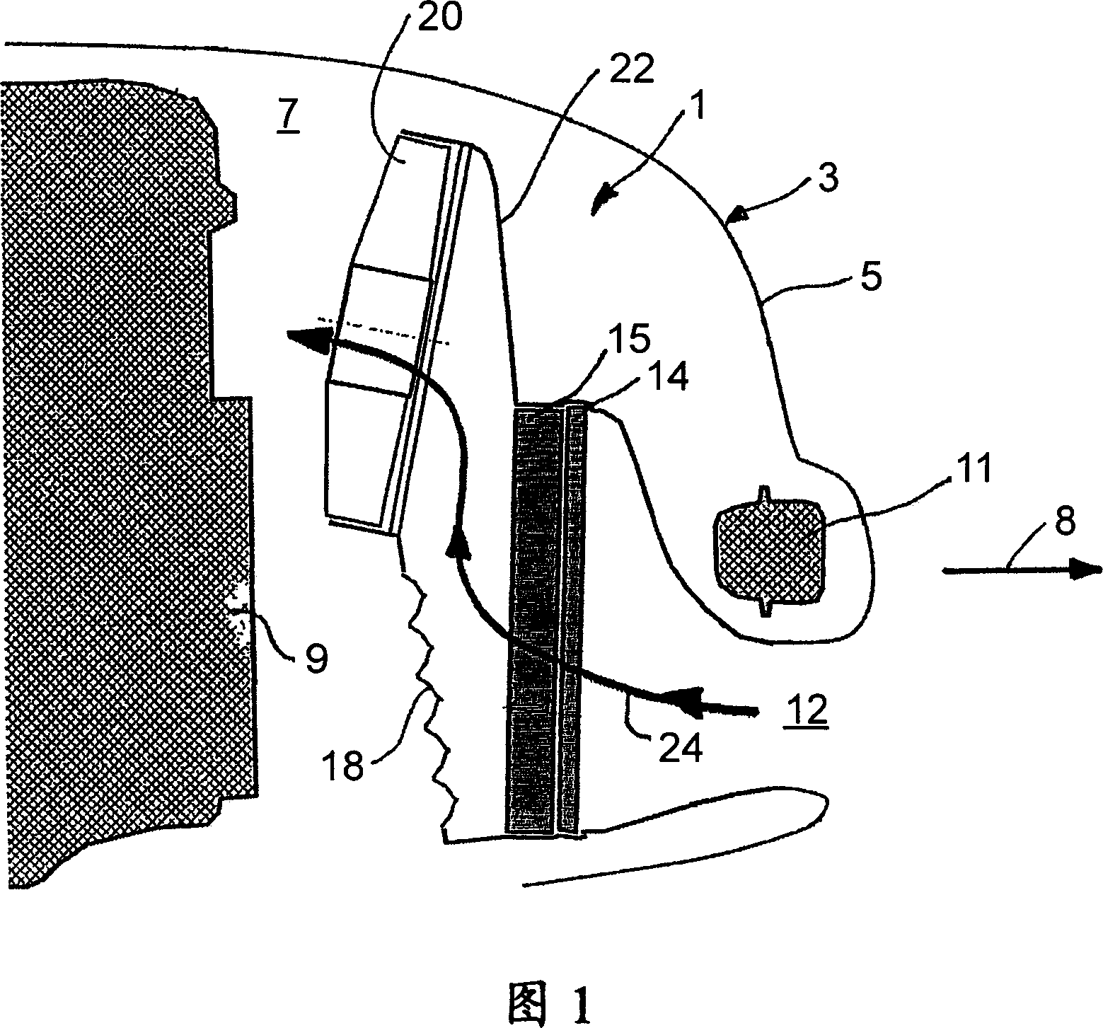
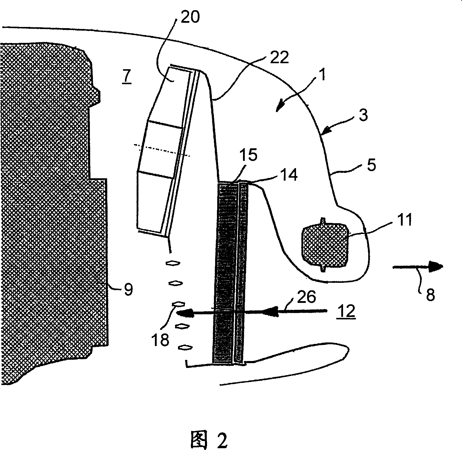
[0036] FIG. 1 shows a schematic diagram of a first exemplary embodiment of a cooling system 1 which is arranged in an engine compartment 7 on a front end 5 of a motor vehicle 3 . When driving forward, motor vehicle 3 moves from left to right in the illustration according to FIG. 1 , as indicated by arrow 8 , which is also defined as the longitudinal direction of the motor vehicle. Cooling system 1 is arranged between engine 9 and front end 5 of motor vehicle 3 .

[0037] A bumper 11 is attached to the front end portion 5 of the motor vehicle 3, and an air intake 12 is provided below the bumper. Alternatively, a plurality of air intakes may be provided below the bumper 11 instead of one air int...


PUM


Abstract

The invention relates to a cooling system (1) for a motor vehicle (3), comprising at least one heat exchanger (14, 15), in particular an intercooler, which is traversed by a medium, in particular a coolant that is used to cool a motor (9) and which comprises a heat exchanger air-penetration surface that is traversed by an air stream along a first stream path (26) in a first operating mode, in particular a back-pressure mode and is additionally or alternatively traversed by an air stream along a second stream path (24) running through an air conduction unit (20) in a second operating mode, in particular a ventilator mode. The air conduction unit is located between the heat exchanger (14, 15) and the motor (9) and comprises a conduction air-penetration surface. The aim of the invention is to provide a cooling system, in which the cooling air stream is obstructed as little as possible along the first stream path (26) in the first operating mode and which permits the cooling air stream to be conducted along the second stream path (24) with minimal loss. To achieve this, the air-conduction device (20) and the heat exchanger (14, 15) are configured and arranged in such a way that a parallel projection of the conduction air-penetration surface in the longitudinal direction (8) of the vehicle (3) on the plane containing the heat-exchanger air-penetration surface, protrudes at least partly beyond said heat-exchanger air-penetration surface and that a significant part of the heat-exchanger air-penetration surface is not covered by the parallel projection of the conduction air-penetration surface.

Description

technical field [0001] The invention relates to a cooling system for a motor vehicle having at least one heat exchanger, in particular a cooler, through which a medium, in particular a coolant, flows, for example for cooling an engine, And the cooler has a heat exchanger-air flow surface through which the airflow flows along the first airflow path in the first operating state, in particular in so-called counter-pressure operation, and in the second operating state In particular in so-called ventilation operation, the air flow additionally or alternatively flows through the air flow surface along a second air flow path which passes through an air delivery device arranged at the heat exchange Between the engine and the engine and it has a conveyor-air flow surface. Background technique [0002] In such cooling systems, the air conveying device is formed, for example, by a fan. The task of the fan is to provide a sufficient flow of cold air through the cooler and the engine c...

Claims


Application Information

Patent Timeline
Patent Type & Authority Applications(China)
IPC IPC(8): F01P11/10B60K11/04F01P5/06B60K11/08
CPCB60K11/085B60K11/04F01P2070/50Y02T10/88
Inventor 斯特凡·罗格
Owner 贝洱公司
Why Eureka
Try Eureka