
Communication network based on master/slave architecture for connecting sensors and actuators

A communication network and control signal technology, applied in the field of servo systems, can solve problems such as insufficient solutions

Inactive Publication Date: 2007-05-09
NEW TRANSDUCERS LTD
View PDF1 Cites 2 Cited by
  • Summary
  • Abstract
  • Description
  • Claims
  • Application Information

AI Technical Summary

Problems solved by technology

[0014] Therefore, even though the time-triggered architecture offers advantages over the event-triggered architecture, it is still not an ideal solution

Method used


Image

  • Communication network based on master/slave architecture for connecting sensors and actuators
  • Communication network based on master/slave architecture for connecting sensors and actuators

Examples


Embodiment Construction

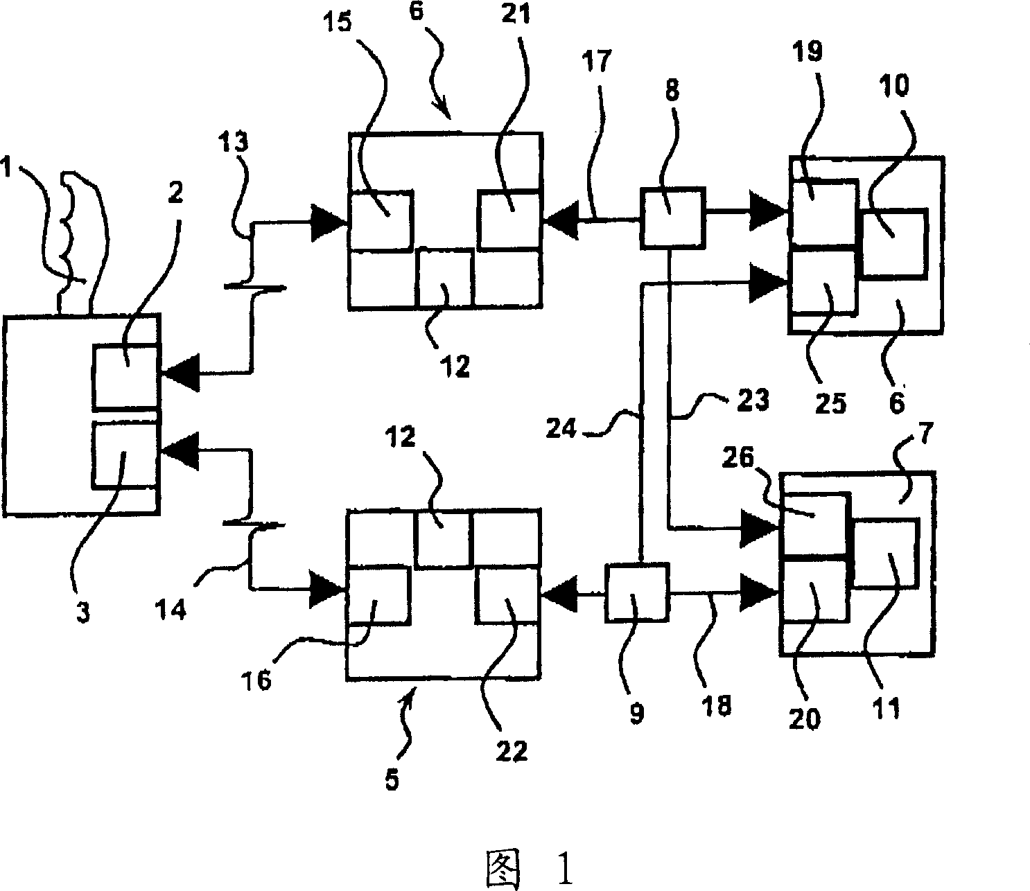
[0072] FIG. 1 shows an aviation application in which a pilot input device 1 has two interfaces, slave nodes 2 and 3 . These nodes are connected by respective transmission lines 13 , 14 to two flight computers 4 , 5 with respective master nodes 15 , 16 . The slave nodes 2 and 3 are accessed by the master nodes 15 and 16 respectively, allowing the computers 4 and 5 to independently make decisions about how to change the flight surfaces 6,7. The timing of the two computers is coordinated by a local time base generator 12 .

[0073] Commands to change the flight surface are then transmitted from the flight computer to the slave nodes 19 , 20 of the respective flight surface CPUs 10 , 11 by the second master node 21 , 22 via routers 8 , 9 and transmission lines 17 , 18 . Those same CPUs then send feedback control signals to the controller via the same path. Redundancy may also be obtained by providing said flight surface CPU 10 , 11 with further slave nodes 25 , 26 cross-connecte...


PUM


Abstract

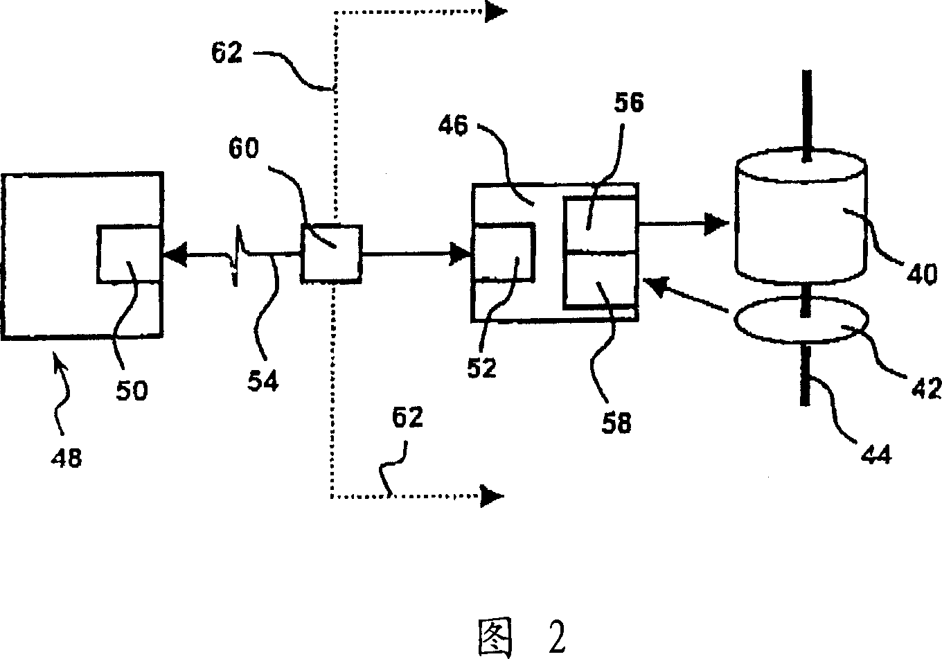
A communications network for servo systems and the like comprises a controller (5; 6; 48), first and second slave nodes (20, 25; 19, 26; 52, 62) configured to respond to control signals from the controller and to send respective feedback control signals to the controller, and a control signal transmission line (18, 24; 17, 23; 54, 62) between the controller and the slave nodes; wherein communication between said controller and said slave nodes employs reflective signaling, and wherein the transmission line incorporates a router (9; 8; 60) configured to route control signals from said controller to one or other of said first and second slave nodes in dependence on a further signal from said controller.

Description

technical field [0001] The present invention is concerned with communication networks, but is not specifically applicable to servo systems. Background technique [0002] The term "fly by wire" is used to describe the use of an electrical connection instead of a mechanical connection in a servo system that connects the manipulator to some kind of machinery. The term is used herein in its broadest sense to encompass such technologies as drive-by-wire, steer-by-wire, brake-by-wire, oil-by-wire, and the like. [0003] The most obvious example of fly-by-wire is embodied in modern aircraft, where navigation controls are handled by computers before being passed on to the flight control surfaces. The technology has been used in aviation for about 35 years (beginning with the Concorde), although the facilities used were extremely expensive. [0004] One of the main areas of development of fly-by-wire technology is in the automotive field. Vehicle manufacturers are enhancing driver...

Claims


Application Information

Patent Timeline
Patent Type & Authority Applications(China)
IPC IPC(8): H04L12/40H04L12/403
CPCH04L2012/40267H04L12/403
Inventor 克里斯托夫·J·考德雷
Owner NEW TRANSDUCERS LTD
Learn More