Magnetic element

A technology of magnetic components and magnetic cores, which is applied in the field of magnetic components and coils including coil brackets, magnetic cores and insulating spacers, can solve the problems that it is difficult to realize the miniaturization of magnetic components, and achieve increased insulation distance and enhanced insulation performance effect

Inactive Publication Date: 2007-05-23
SUMIDA ELECTRIC H K COMPANY
View PDF1 Cites 0 Cited by
  • Summary
  • Abstract
  • Description
  • Claims
  • Application Information

AI Technical Summary

Problems solved by technology

This makes it difficult to...

Method used


Image

  • Magnetic element
  • Magnetic element
  • Magnetic element

Examples


Embodiment Construction

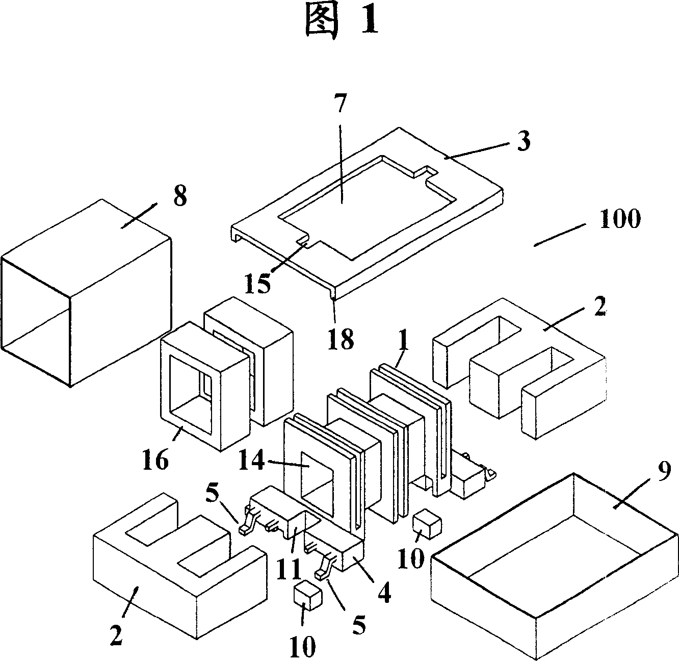
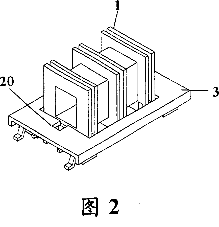
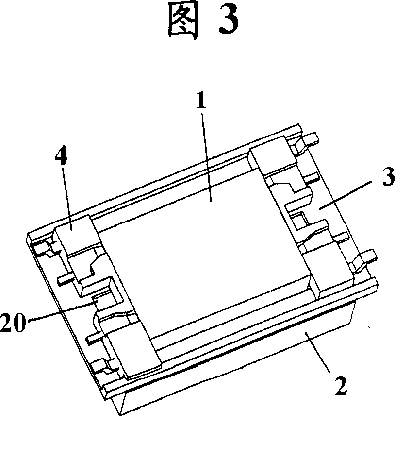
[0031] Referring to Figures 1 to 4, there is shown a magnetic element 100 according to a first embodiment of the present invention. As shown in FIG. 1 , the magnetic element 100 roughly includes a coil support 1 , a coil 6 , an insulating spacer 3 and a pair of magnetic cores 2 . The magnetic core 2 is a magnetic core similar to an "E" shape, which can be made of manganese-zinc alloy. The coil support 1 is a conventional type of coil support, which preferably consists of a liquid crystal polymer (LCP) material. The coil holder 1 includes a main body and bases 4 at both ends thereof. In the body of the coil holder 1 there is provided an opening 14 which is sized to allow the middle arm of the E-shaped magnetic core 2 to be inserted thereinto. Several coil terminals 5 are provided on each substrate 4 , two coil terminals 5 are shown in the figure. The insulating spacers 3 are likewise preferably made of a liquid crystal polymer (LCP) material and have a thickness of, for exam...


PUM


Abstract

The invention relates to a magnetic element, which comprises winding support with terminal base; winding coiled on the winding support; insulated baffle plate with hollow open to cover the base via the winding support; and the magnetic corn inserted into the winding support, wherein said base has the first positioning part; the baffle plate has second positioning part; the first and second positioning part can form adhesive stuff part through to the magnetic corn via mounting winding support, magnetic corn and insulated baffle plate together; therefore, it only needs to fill stuff into stuff part, to fix winding support, magnetic corn and baffle plate together. The invention can reduce cost and simplify process.

Description

technical field [0001] The invention relates to a magnetic element, in particular to a magnetic element comprising a coil support, a coil, a magnetic core and an insulating spacer. Background technique [0002] Magnetic components are a basic component with a wide range of applications. In order to meet the needs of modern communication, computer, audio-visual equipment, and automotive electronic systems, it is hoped to provide miniaturized magnetic components with stable electrical characteristics at low cost. [0003] For example, Japanese Laid-Open Utility Model Publication Kokai Hei 7-29812 discloses a magnetic element. As shown in FIG. 13 , the magnetic element roughly includes a coil support 2 , a coil 4 , an insulating spacer assembly 6 and a pair of E-shaped magnetic cores 5 . The coil holder 2 includes a main body provided with a central through hole 2b, and a base 1 with terminals 3a at both ends thereof. The insulating spacer assembly 6 includes an insulating s...

Claims


Application Information

Patent Timeline
IPC IPC(8): H01F30/06H01F27/32
Inventor 杨小汉
Owner SUMIDA ELECTRIC H K COMPANY
Why Eureka
Try Eureka