Optical film, method for producing same, and polymer liquid crystal particle
A technology of optical thin films and polymers, applied in chemical instruments and methods, optics, liquid crystal materials, etc.
- Summary
- Abstract
- Description
- Claims
- Application Information
AI Technical Summary
Problems solved by technology
Method used
Image
Examples
Embodiment 1
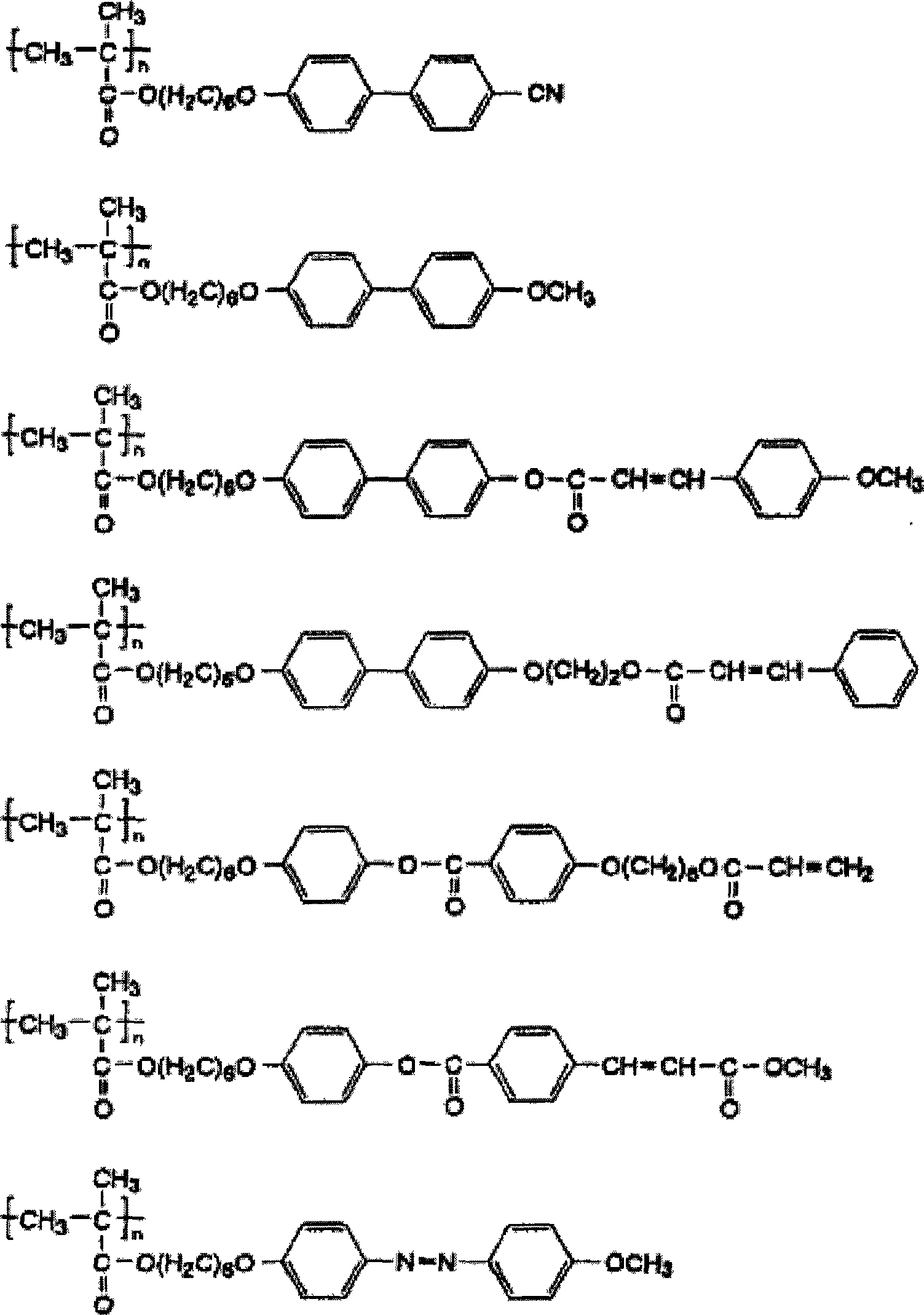
[0047] 3.0 g of a compound represented by the following formula (1) as a polymerizable monomer, 2.0 g of a compound represented by the following formula (2), and 0.02 g of 2,2'-azobisisobutyronitrile as a polymerization initiator 200 ml of a 0.10% aqueous solution of polyvinyl alcohol was mixed at 5° C. to obtain a reaction liquid of a polymerizable monomer.
[0048] The reaction solution of the above-mentioned polymerizable monomer was stirred at 5000 rpm with a homogenizer to prepare an emulsion of the polymerizable monomer. Furthermore, the emulsion was heated and polymerized at 80° C. for 5 hours while stirring at 5000 rpm with a homogenizer in a nitrogen atmosphere, and then filtered to obtain 4.3 parts of polymer liquid crystal particles. As a result of observing the shape of the obtained polymer liquid crystal particles with a scanning electron microscope, they were spherical. As a result of measuring the particle diameter by the Coulter counter method, it was 5.1 μm, ...
Embodiment 2
[0052] 3.0 g of the compound represented by the above formula (1) as a polymerizable monomer, 2.0 g of the compound represented by the above formula (2), 0.02 g of 2,2'-azobisisobutyronitrile as a polymerization initiator, It mixed in 200 ml of THF at 5 degreeC, and obtained the reaction liquid of a polymerizable monomer. Under a nitrogen atmosphere, the polymerizable monomer reaction solution was heated and polymerized at 54° C. for 24 hours while stirring with a magnetic stirrer, and then cooled and filtered to obtain 4.1 g of a white polymer liquid crystal compound. The volume average molecular weight of the polymer liquid crystal compound measured by GPC was about 80,000.
[0053] Next, 2.0 g of the above-mentioned polymer liquid crystal compound was mixed into 20 g of anisole, and heated and dissolved at 80° C. to obtain a solution. Furthermore, after cooling the obtained solution to 5 degreeC, it filtered and obtained 1.9 g of polymer liquid crystal microparticles|fine-...
Embodiment 3
[0055] 2.0 g of the polymer liquid crystal compound obtained in Example 2 was dissolved in 40 g of chloroform to obtain a solution. Next, this solution was sprayed into droplets with a particle diameter of 10 μm by a spray dryer, and dried with hot air at 100° C. to obtain 0.6 g of polymer liquid crystal particles. As a result of observing the shape of the obtained polymer liquid crystal particles with a scanning electron microscope, they were spherical. As a result of measuring the particle diameter by the Coulter counter method, it was 4.0 μm.
PUM
| Property | Measurement | Unit |
|---|---|---|
| mean roughness | aaaaa | aaaaa |
| particle size | aaaaa | aaaaa |
| mean roughness | aaaaa | aaaaa |
Abstract
Description
Claims
Application Information
 - R&D
- Intellectual Property
- Life Sciences
- Materials
- Tech Scout
- Unparalleled Data Quality
- Higher Quality Content
- 60% Fewer Hallucinations
Browse by: Latest US Patents, China's latest patents, Technical Efficacy Thesaurus, Application Domain, Technology Topic, Popular Technical Reports.
© 2025 PatSnap. All rights reserved.Legal|Privacy policy|Modern Slavery Act Transparency Statement|Sitemap|About US| Contact US: help@patsnap.com


