Phase developing method

A phase unwrapping and phase technology, which is applied in the field of signal processing, can solve problems such as the inaccessibility of the integration path, the increase in the calculation amount and difficulty of branch setting, and the complexity of the best path selection, so as to eliminate the isolated area phenomenon, small error, and eliminate noise Effect

Inactive Publication Date: 2007-06-06
SHANGHAI INST OF OPTICS & FINE MECHANICS CHINESE ACAD OF SCI
View PDF0 Cites 7 Cited by
  • Summary
  • Abstract
  • Description
  • Claims
  • Application Information

AI Technical Summary

Problems solved by technology

Obviously, when there are few residual points, the connection of branches is simple and clear, but as the number of residual points increases, the calculation amount and difficulty...

Method used


Image

  • Phase developing method
  • Phase developing method
  • Phase developing method

Examples


Embodiment Construction

[0039] The present invention will be further described below in conjunction with the accompanying drawings and embodiments, but the protection scope of the present invention should not be limited thereby.

[0040] The following uses the interferometer that detects the surface shape of an optical element as an example to specifically illustrate the method for phase unwrapping of the present invention:

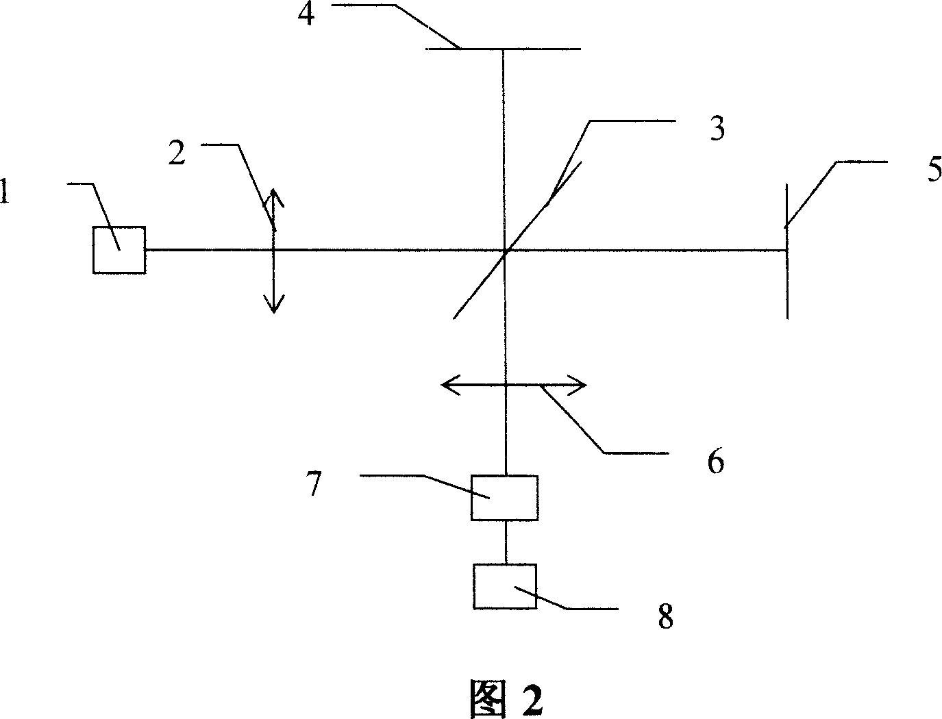
[0041] The surface shape of the optical element is detected by a Tieman-Green interferometer, and the device is shown in Figure 2. First, the light is emitted from the He-Ne laser 1, passes through the collimating mirror 2 and reaches the beam splitter 3 so that the beam is divided into two paths, and one path returns through the reference surface 4, wherein the reference surface 4 can be driven by piezoelectric ceramics to achieve phase shifting, and the other path of the beam passes through the waiting The surface 5 of the measuring element returns, and the two light beams mee...


PUM


Abstract

The invention is a phase unwrapping method to process coherent waves. The feature is: first to do vector filter on the phases containing remnant pixel, then to unwrap phases with reliability phase unwrapping method. The mentioned vector filter is to compute sine and cosine value of each pixel in the phase, and perform the average filtering on the continuous sine and cosine images, finally obtain the phase value of filtered interference image by inverse mapping; then wrap the phases with reliability phase unwrapping method: first construct the reliability, then wrap the phases in order according to the value of reliability.

Description

technical field [0001] The invention relates to signal processing, in particular to a method for phase unwrapping of coherent wave information processing. It is used in phase-shifting interferometry, synthetic aperture radar and medical nuclear magnetic resonance and other fields. Background technique [0002] When it comes to coherent wave information processing, as long as the information of the processing object is represented by phase, the expression of arctangent function is used in the process of extracting phase information, and the phase expressed by arctangent function needs to be restored to the original phase distribution. This process called phase unwrapping. [0003] The original data measured by the phase-shifting interferometer is an interferogram. The light intensity distribution of the interferogram is represented by I, then the light intensity distribution of the interference field coordinates (x, y) is: [0004] I(x,y,t)=a(x,y)+b(x,y)cos[φ(x,y)+δ(t)] (1...

Claims


Application Information

Patent Timeline
IPC IPC(8): G06F17/00G06F19/00G01B9/02G01J9/02G01S13/90G01S7/02G01R33/54
Inventor 李永国朱健强
Owner SHANGHAI INST OF OPTICS & FINE MECHANICS CHINESE ACAD OF SCI
Why Eureka
Try Eureka