High gain isolating active clamping boost transducer

An isolated, high-gain technology, applied in the direction of converting DC power input to DC power output, instruments, and adjusting electrical variables, can solve problems such as insufficient output voltage gain, large current stress of power switch tubes, and large switching losses. Achieve the effect of improving circuit efficiency, increasing output gain, and reducing additional components

Active Publication Date: 2007-06-06
ZHEJIANG UNIV
View PDF0 Cites 9 Cited by
  • Summary
  • Abstract
  • Description
  • Claims
  • Application Information

AI Technical Summary

Problems solved by technology

This kind of flyback interleaved parallel DC-DC converter is a hard switching operation, the switching loss is large, and the input voltage can be adjusted in a wide range, but the output voltage gain is not large enough, and the leakage inductance energy causes the first power switch tube, the second power switch The voltage spike of the switching tube, the efficiency is low
In recent years, some isolated high-gain boost topologies have been studied successively, one of wh

Method used


Image

  • High gain isolating active clamping boost transducer

Examples


Embodiment Construction

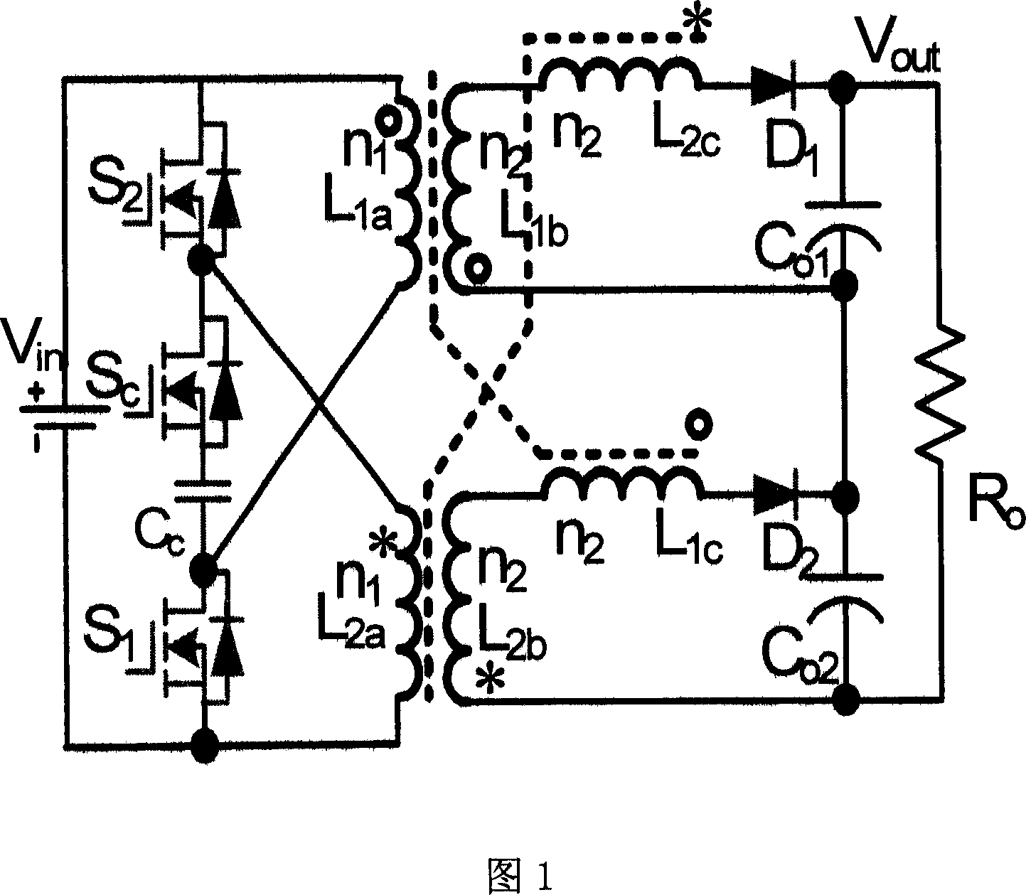
[0008] Referring to Fig. 1, the high-gain isolated active clamp boost converter of the present invention includes two power switch tubes S1, S2, two freewheeling diodes D1, D2, two output capacitors Co1, Co2 and two Coupled inductor, the first coupled inductor has three windings L1a, L1b, L1c, the second coupled inductor has three windings L2a, L2b, L2c, the drain of the first power switch tube S1 is connected to one end of the first winding L1a of the first coupled inductor The source of the first power switch tube S1 is connected to one end of the first winding L2a of the second coupled inductor, the source of the second power switch tube S2 is connected to the other end of the first winding L2a of the second coupled inductor, and the second The drain of the second power switch tube S2 is connected to the other end of the first winding L1a of the first coupled inductor, one end of the second winding L1b of the first coupled inductor is connected to one end of the third windin...


PUM


Abstract

An active clamping-boosting inverter of high-gain isolation type is prepared as realizing high gain output of said inverter by series-connecting the third winding to output capacity of two coupled inductances, absorbing and transferring leakage energy of two coupled inductances nondestructively by series circuit prepared by the first clamping capacity and the first auxiliary switching tube, utilizing series circuit and parallel capacity to realize zero voltage turn on and turn off of said auxiliary switch.

Description

technical field [0001] The invention relates to a DC-DC converter, in particular to a high-gain isolated active clamp boost converter. Background technique [0002] A conventional flyback (Flyback) interleaved parallel DC-DC converter includes two coupled inductors, two freewheeling diodes, two power switches, an output capacitor, and the drain of the first power switch is connected to the first coupling One end of the first winding of the inductor is connected, the drain of the second power switch is connected to one end of the first winding of the second coupled inductor, and the other end of the first winding of the first coupled inductor is connected to the first winding of the second coupled inductor One end of the second winding of the first coupled inductor is connected to the anode of the first diode, one end of the second winding of the second coupled inductor is connected to the anode of the second diode, and the first diode The cathode of the second diode is conn...

Claims


Application Information

Patent Timeline
IPC IPC(8): H02M3/335
Inventor 何湘宁李武华吴建德
Owner ZHEJIANG UNIV
Why Eureka
Try Eureka