Micro-jet-flow water-cooling system for luminuous diode LED

A light-emitting diode and cooling system technology, which is applied in the cooling/heating device, cooling/ventilation/heating transformation of lighting devices, lighting devices, etc., can solve the problems of not being able to meet the temperature requirements of LEDs, and achieve large heat transfer coefficients and flexible control , Good heat exchange effect

Inactive Publication Date: 2007-06-13
刘胜
View PDF0 Cites 31 Cited by
  • Summary
  • Abstract
  • Description
  • Claims
  • Application Information

AI Technical Summary

Problems solved by technology

[0005] In recent years, with the continuous expansion of the application range of LEDs, more and more attention has been paid to high-power LED groups. The above-mentioned traditional cooling methods can no longer meet the temperature requirements of LEDs.

Method used


Image

  • Micro-jet-flow water-cooling system for luminuous diode LED
  • Micro-jet-flow water-cooling system for luminuous diode LED
  • Micro-jet-flow water-cooling system for luminuous diode LED

Examples


Embodiment 1

[0017] Embodiments of the present invention are further described below in conjunction with the accompanying drawings:

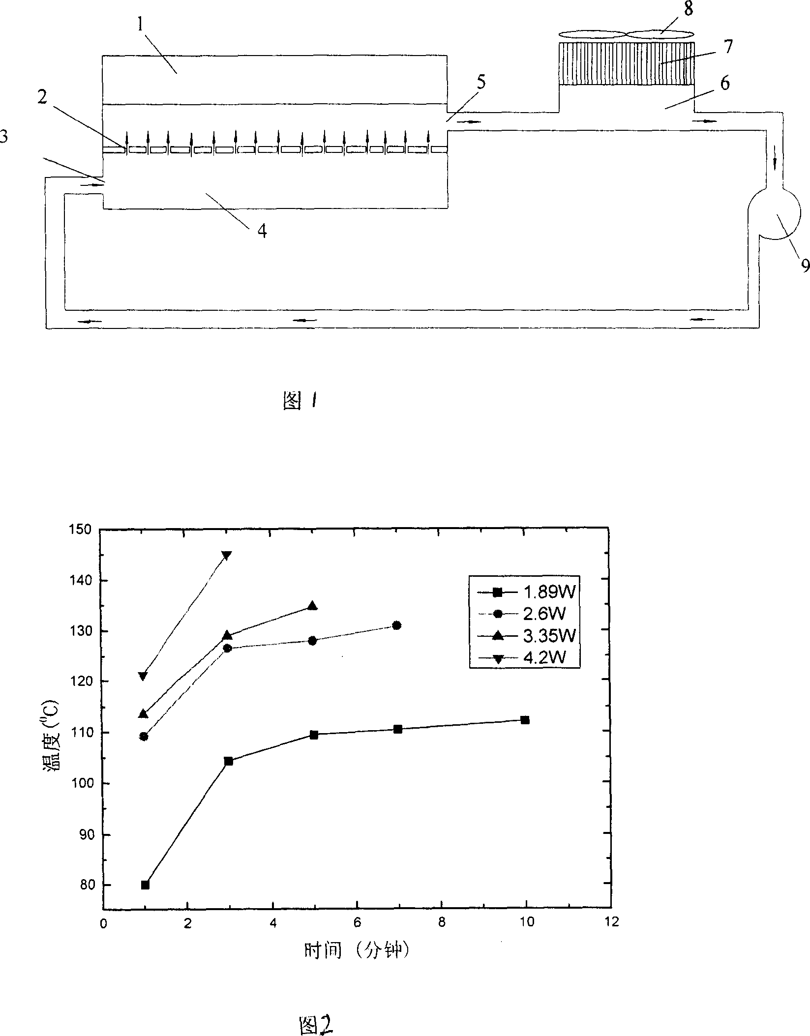
[0018] The lower surface of the base 1 of the LED chip is installed on the shell of the micro jet, and the micro jet is made of carbon nanotubes, high thermal conductivity metal, diamond and other high thermal conductivity materials. The outer surface of the micro jet is connected with the lower surface of the base 1 of the LED chip by using heat conduction paste to increase the heat conduction effect. A cavity 4 is provided in the micro-jet, and the middle of the micro-jet cavity 4 is divided into upper and lower two monomers 10, 12 by a partition plate 2 with a plurality of micro-spouts. The micro-jet adopts Carbon nanotubes, high thermal conductivity metals, diamonds and other high thermal conductivity materials. Both sides of the cavity 4 are respectively provided with a cooling water inlet 3 and a cooling water outlet 5, the cooling water inlet 3 is co...

Embodiment 2

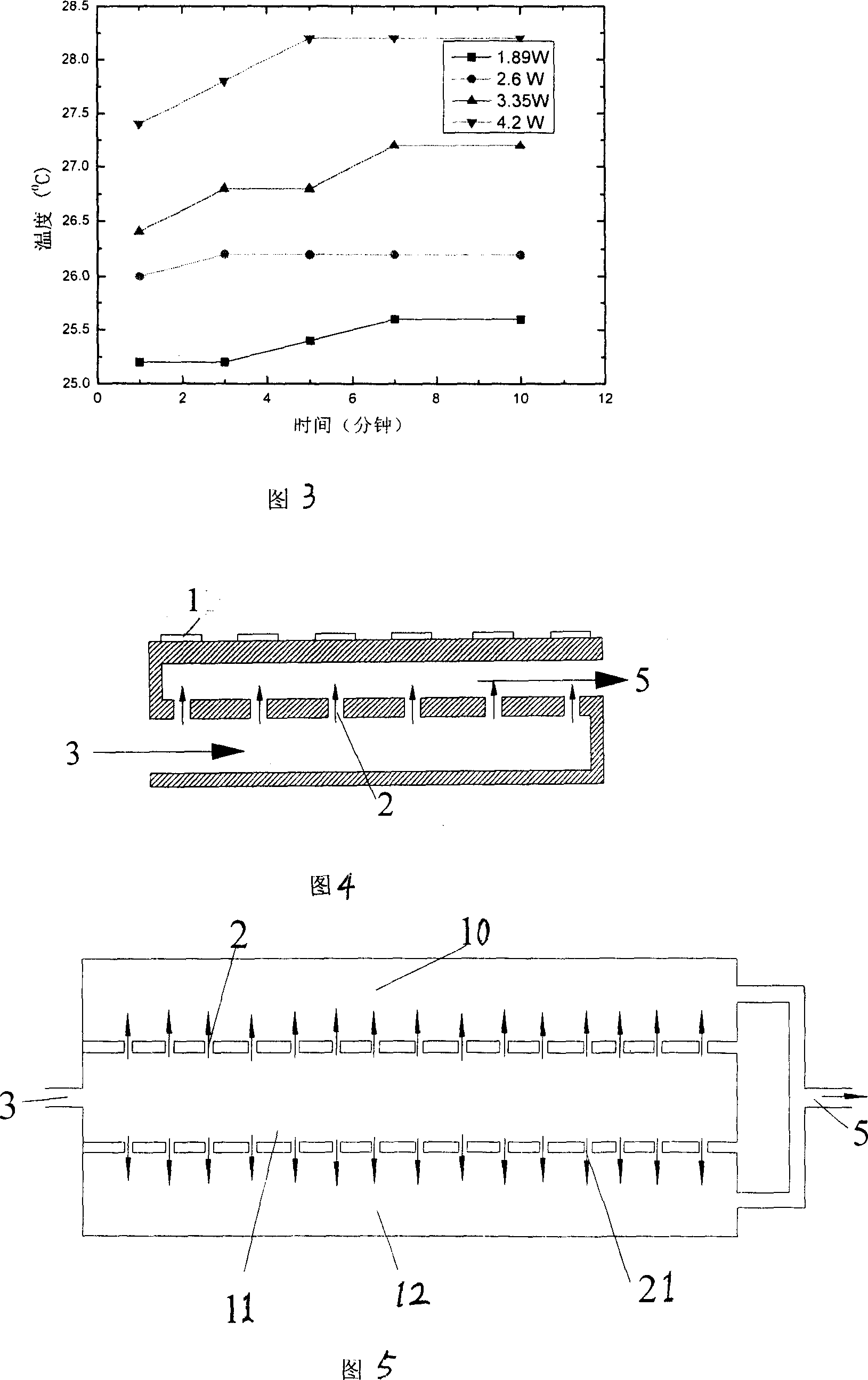
[0022] Embodiment 2 is the same as Embodiment 1, except that Embodiment 1 adopts the middle of the micro-jet fluidizer cavity to be divided into upper and lower two monomers 10, 12 by a partition plate 2 with a plurality of micro-orifices. And embodiment 2 is divided into upper, middle and lower three monomers 10, 11, 12 by two partitions 2 with a plurality of micro nozzles. This design is mainly to cool the double-sided LED chipset. See Figure 5. In the figure, the cooling water flows in from the inlet 3 and enters the middle monomer 11 of the micro-jet cavity. Under the action of pressure, the cooling water forms jets at the nozzles 2 on both sides respectively, and impacts on the base 1 of the LED chip. On the inner side of the contact surface of the micro-jet fluidizers whose lower surfaces are closely connected, the cooling water after heat exchange respectively flows out from the lower monomer 12 and the upper monomer 10 and joins at the outlet 5, and re-enters the main...

Embodiment 3

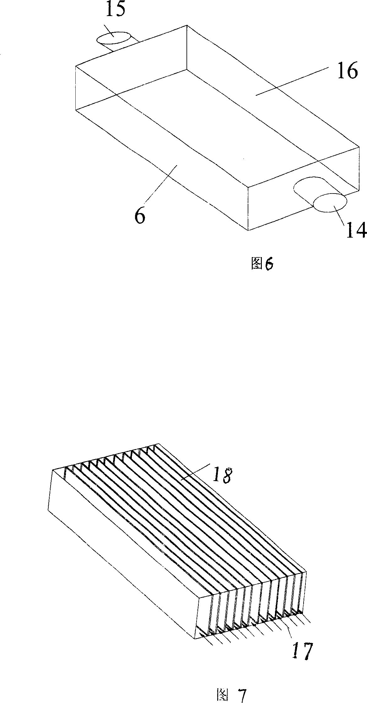
[0024] Embodiment 3 is the same as Embodiment 2, except that in Embodiment 3, the cold plate 18 etched with microchannels is directly installed inside the water tank 6 . When the heated water flows in from the water tank inlet 14, after flowing to the cold plate 18 etched with microchannels, it will be divided into many streams of small fluids, and then flow out from the water tank outlet 15 confluence. Due to the use of micro-channels, the heat transfer coefficient will be greatly enhanced, and the heat in the water will be quickly transferred to the water tank. After the cooling effect of the heat sink and the fan, the heat will be diffused to the environment as soon as possible. See Figure 7.


PUM


Abstract

The system includes LED chip, micro jet ejector, water tank with cooling unit, and tiny pump. Base seat of LED chip is installed on shell of the micro jet ejector. A cavity is setup inside the micro jet ejector. There is clapboard with multiple tiny nozzles inside the cavity. Through tubes, inlets and outlets setup on two sides of the clapboard are connected to tiny pump and water tank. Heat sink and fan in up part of the water tank, and micro flute channels inside the water tank form a close internal circulation cooling system. Using impaction heat exchange, the system possesses large heat transfer coefficient. Advantages are: flexible control for setting cooling direction. The invention is suitable to cool LED where condition is changed quite often.

Description

technical field [0001] The invention relates to a cooling system for light-emitting diodes (LEDs), in particular to a micro-jet water cooling system for light-emitting diodes (LEDs). technical background [0002] In recent years, the new light-emitting diode (LED) light source has been widely used in industrial equipment, instruments, traffic lights, automobiles, etc. , Backlight and other fields. [0003] Theoretically speaking, most of the electrical energy can be converted into light energy by properly matching the materials, manufacturing process and operating temperature. But what needs to be pointed out in particular is that the temperature at the PN junction has a huge impact on the deviation of the light output color of the LED and the reliability of the light source itself. For high-power LED light sources, proper design must be used to keep the LED illuminant package at the rated normal operating temperature, that is, to set a limit on the junction temperature to...

Claims


Application Information

Patent Timeline
Patent Type & Authority Applications(China)
IPC IPC(8): H01L23/34H01L23/473F21V29/00H05K7/20F21V29/503F21V29/56
Inventor 刘胜罗小兵
Owner 刘胜
Why Eureka
Try Eureka