
Allocation wiring structure of printing circuit board

A printed circuit board and wiring structure technology, which is applied in the fields of communication and electronics, can solve problems such as the inability to effectively control the direction of heat flow, and achieve the effects of convenient and reliable implementation, avoiding excessive temperature, and good heat dissipation

Inactive Publication Date: 2007-06-20
HUAWEI TECH CO LTD
View PDF0 Cites 8 Cited by
  • Summary
  • Abstract
  • Description
  • Claims
  • Application Information

AI Technical Summary

Problems solved by technology

[0009] The problem to be solved by the present invention is to provide a printed circuit board layout and wiring structure to overcome the defect that the heat of the heating chip is mainly transmitted to the direction of the PCB and cannot effectively control the direction of heat flow

Method used


Image

  • Allocation wiring structure of printing circuit board
  • Allocation wiring structure of printing circuit board
  • Allocation wiring structure of printing circuit board

Examples


Embodiment Construction

[0033] Below in conjunction with accompanying drawing and embodiment, the specific embodiment of the present invention is described in further detail:

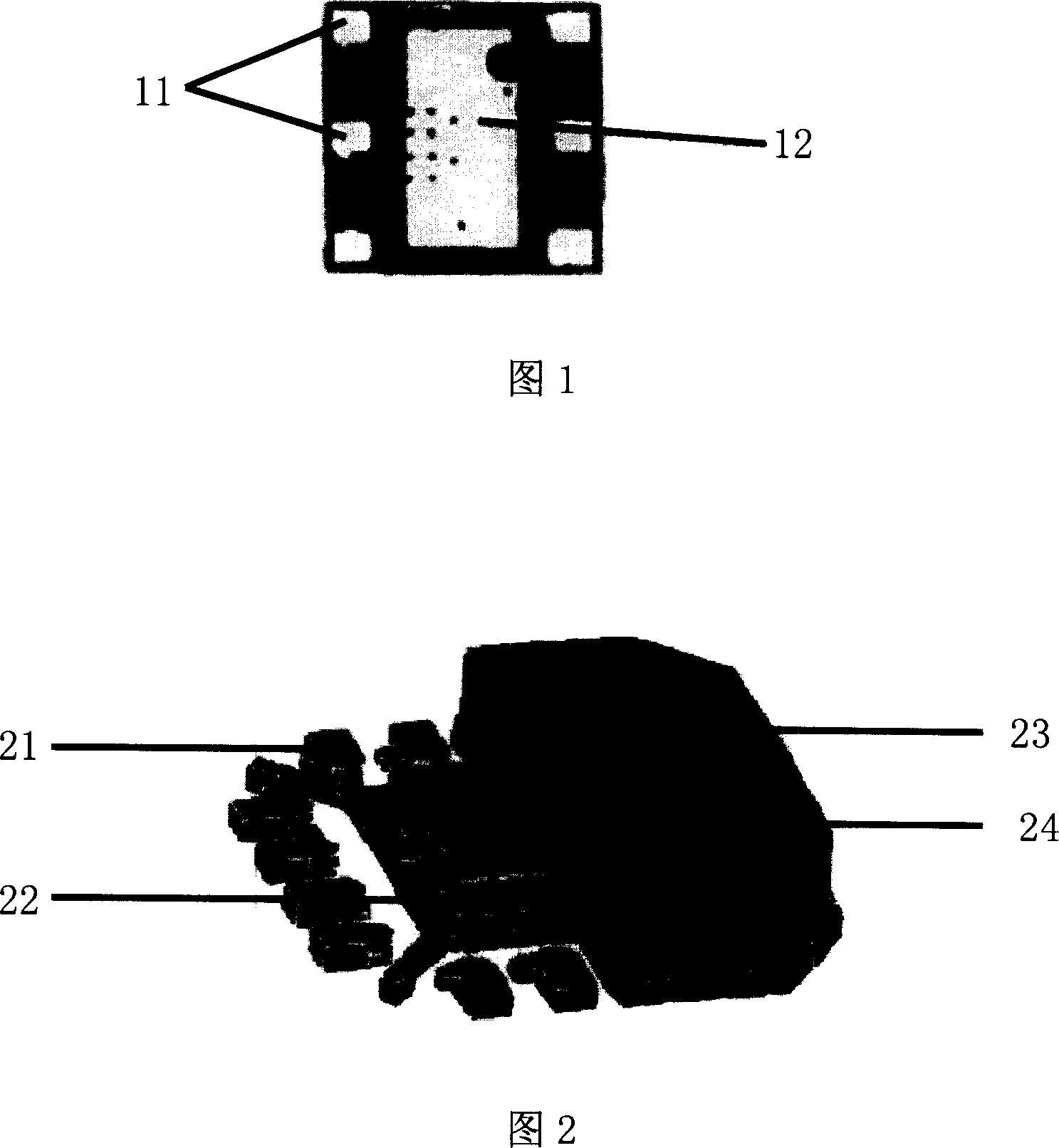
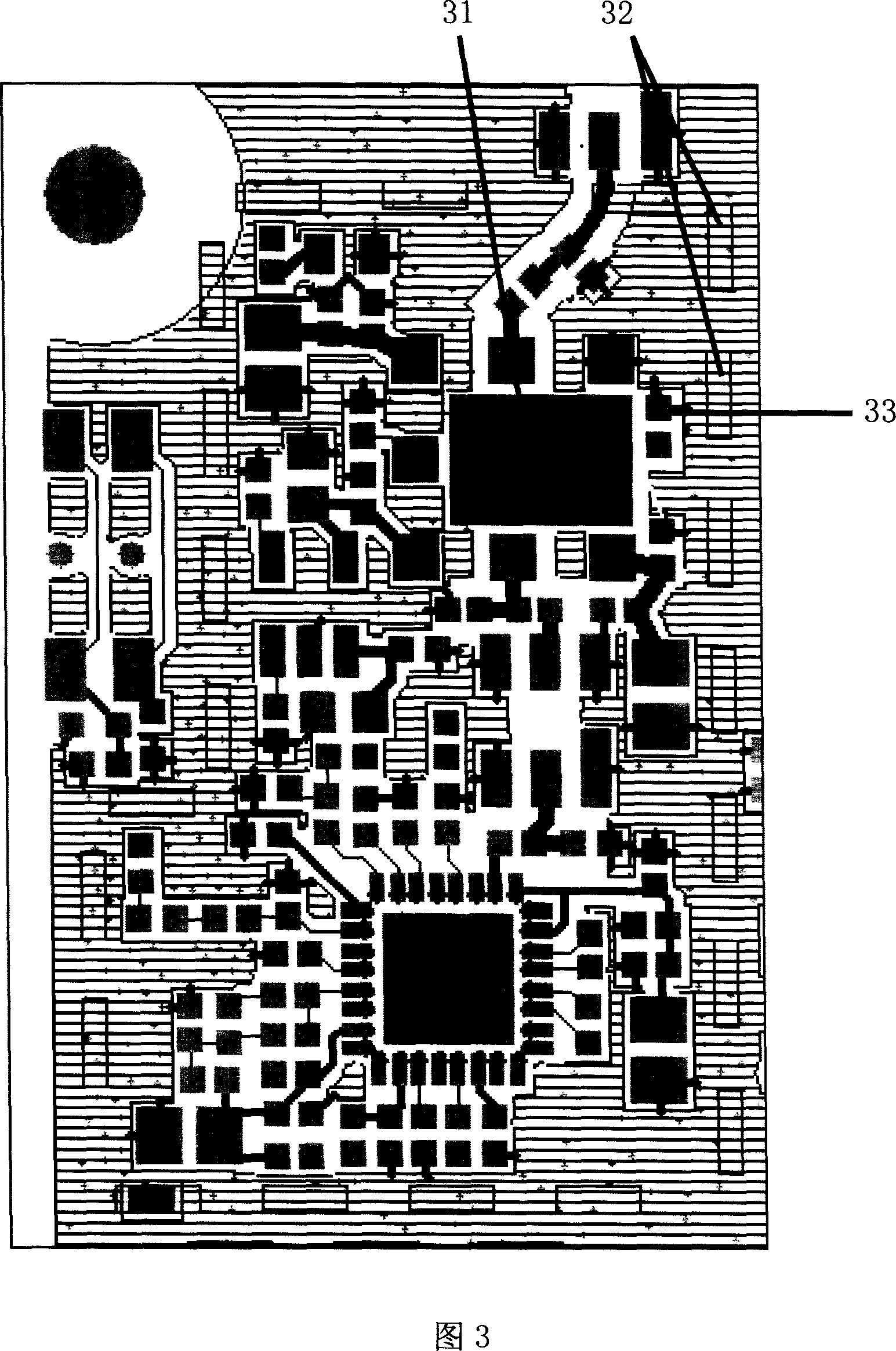
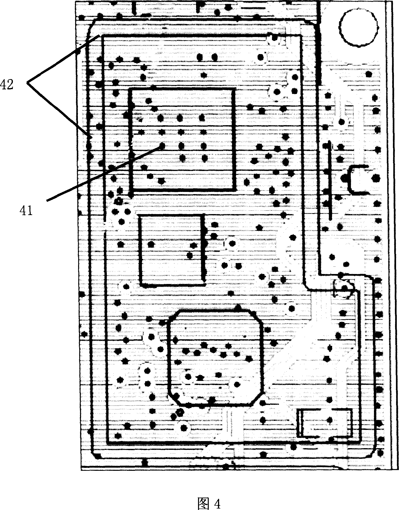
[0034] The wiring diagram of the PCB surface layer of a device according to the present invention is shown in FIG. 9 , and the wiring diagram of a certain layer of the inner layer of the PCB is shown in FIG. 10 . Referring to Fig. 9 and Fig. 10, the heating chip of the present invention is a PA chip, and a pad 91 is provided on the PCB under the thermal pad of the PA chip, and a certain number of thermal vias 101 are opened on the pad, and 92 are metal vias. The pad of the shielding box, 102 is the projection position of the metal shielding box on this layer, and 93 is the copper skin connecting the pad 91 and the pad 92 of the metal shielding box.

[0035]Compared with the existing heat dissipation structure shown in Fig. 3 and Fig. 4, in the present invention, the pad 91 under the PA chip and the metal shielding box pad 92 a...


PUM

PropertyMeasurementUnit
Lengthaaaaaaaaaa

Abstract

The invention is used for overcoming the heat of chip transmitted to PCB. It comprises: the bounding pad of the heated chip and the bounding pad of metallic shielding box, both are connected using copper sheet. The heat via holes or heat buried holes or heat blind holes under the bounding pad of the heated chip has less quantities and densities, and the copper pour on the portion of PCB except the top portion of PCB is less than the top portion of PCB near the heated chip. By the invention the heat from BCP is transmitted to direction of the metallic shielding box.

Description

technical field [0001] The invention relates to the technical fields of communication and electronics, in particular to a layout and wiring structure of a printed circuit board. Background technique [0002] With the development of wireless communication and chip packaging technology, more and more functions are integrated into mobile phones. The power consumption of mobile phones also increases significantly accordingly, especially in the third-generation mobile phones. The third-generation mobile phone adopts CDMA2000 (Code-Division Multiple Access) or WCDMA (Wideband CDMA, wideband code-division multiple access) technology, and the efficiency of the PA (Power Amplifier, power amplifier) ​​chip used in this technology is much lower than that used The second-generation mobile phone PA chip of GSM (GlobalSystem for Mobile Communications, Global System for Mobile Communications) technology. When transmitting at maximum power, the heat consumption of the third-generation mob...

Claims


Application Information

Patent Timeline
IPC IPC(8): H05K1/18H05K7/20
Inventor 靳林芳范勇
Owner HUAWEI TECH CO LTD
Learn More