AC servo system with distribution type motion controller

A motion control and distributed technology, applied in the field of AC servo system, can solve problems such as complex wiring, susceptibility to noise interference, and limited command signals

Active Publication Date: 2007-07-11
DELTA ELECTRONICS INC
View PDF0 Cites 11 Cited by
  • Summary
  • Abstract
  • Description
  • Claims
  • Application Information

AI Technical Summary

Problems solved by technology

[0004] (1) The cost is too high: the more axes the host controller 16 corresponds to, the heavier the calculations to be performed, and the higher the level requirement of the CPU (not shown) in the host controller 16
[0005] (2) The number of axes is limited: the number of axes of the servo drive 12 is limited by the level of the CPU and the number of channels of the hardware
[0006] (3) Complicated wiring: A / D (analog / digital), D / A (digital / analog), command pulse, feedback pulse, digital input / output, etc. between the host controller 16 and the servo drive 12 line is very complicated
[0007] (4) Insufficient resolution: the command signal is limited by physical signals, such as A / D conversion resolution or pulse frequency
[0008] (5) Susceptible to environmental interference: In the harsh environment of the factory, there is a great chance that the analog signal will be interfered
[0009] (6) Difficult to maintain: the more axes the servo drive 12 has, the greater the corresponding wiring. If there is a problem with the system, it is extremely difficult to check the wiring
[0011] (1) Higher cost: High-speed communication means that it is more susceptible to noise interference. In the harsh environment of the factory, high-standard communication hardware, such as optical fiber, must often be used, which makes the cost even higher
[0012] (2) Special specifications: This kind of high-speed real-time communication network 18 is usually a special industrial specification, such as SSC-Net or Sercos. The system must be purchased in a complete set, which cannot meet the needs of customers who develop their own systems or have special application requirements

Method used


Image

  • AC servo system with distribution type motion controller
  • AC servo system with distribution type motion controller
  • AC servo system with distribution type motion controller

Examples


Embodiment Construction

[0034] Preferred embodiments of the present invention will be described below with reference to the accompanying drawings.

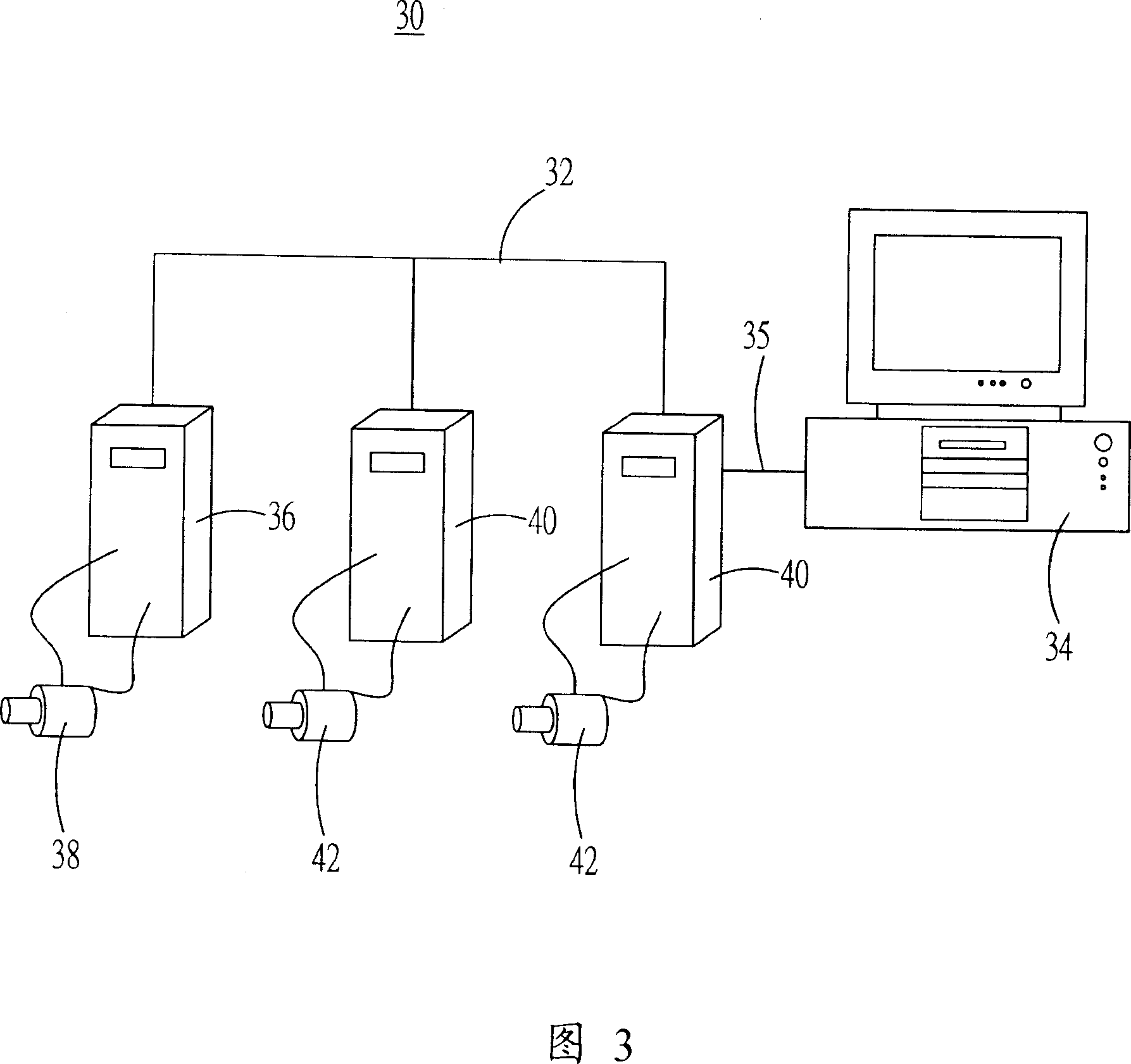
[0035] FIG. 3 is a structural diagram of an AC servo system with distributed multi-axis motion control according to the present invention. In FIG. 3 , a distributed multi-axis motion control system 30 is used for multi-axis control. The system has a communication network 32, a spindle driver 36 is coupled to the communication network 32, a spindle motor 38 is coupled to the spindle driver 36, and multiple slaves The shaft driver 40 is coupled to the communication network 32 , a plurality of slave shaft motors 42 are coupled to the slave shaft driver 40 , and a personal computer or man-machine interface 34 is coupled to any shaft driver via a transmission line 35 . Wherein, the communication network 32 is composed of a CAN bus, and the main shaft motor 38 and the slave shaft motor 42 are AC servo motors.

[0036] The written software control program and ...


PUM


Abstract

The alternating current servomechanism with distributional movement control comprises programmable movement controller of each drive to execute customized program to control the motor action of the shaft or the other shafts and input and output signal, downloading and executing movement program through telecommunication network, compiling parameters of each shaft, monitoring the status of each shaft, deciding master or slave shaft based on requirements of the drive, with the main drive executing multi shafts synchronic action program, sending orders to slave shaft through telecommunication network, with the master drive calculates the compensatory order coordinate of each shafts based on the path order and the slave shaft drive and the received path order to make the moving track of the master and slave shafts conforming to the path orders.

Description

technical field [0001] The invention relates to an AC servo system. The system includes multiple motor drivers. In addition to the traditional function (driving the servo motor), a motion control unit is added in the motor driver, which is especially suitable for forming a distributed multi-axis motion control system. . Background technique [0002] At present, the system architecture of multi-axis motion control belongs to centralized control, that is, it includes the upper controller, which controls the servo drive to perform multi-axis interpolation motion such as linear / arc through traditional wiring or high-speed communication as described below. . [0003] FIG. 1 is an architecture diagram of a centralized control system for multi-axis motion control in the prior art. In the architecture, the command planning of the multi-axis tweening of the servo drive 12 and the control of the I / O (input / output) 14 are centralized. Processed by the host controller 16, the signal o...

Claims


Application Information

Patent Timeline
IPC IPC(8): G05B19/418
CPCY02P90/02
Inventor 周中奇陈建达蔡清雄
Owner DELTA ELECTRONICS INC
Why Eureka
Try Eureka