

The method of the orientation profiling of the lanthanide permanent magnet and preparation device for the same
A rare-earth permanent magnet, press-molded technology, applied in the direction of permanent magnet, inductor/transformer/magnet manufacturing, inorganic material magnetism, etc., can solve the problem of excessive production cost, achieve the effect of reducing power consumption, reducing manufacturing cost, and reducing volume
- Summary
- Abstract
- Description
- Claims
- Application Information
AI Technical Summary
Problems solved by technology
Method used
Image

Examples
example 1
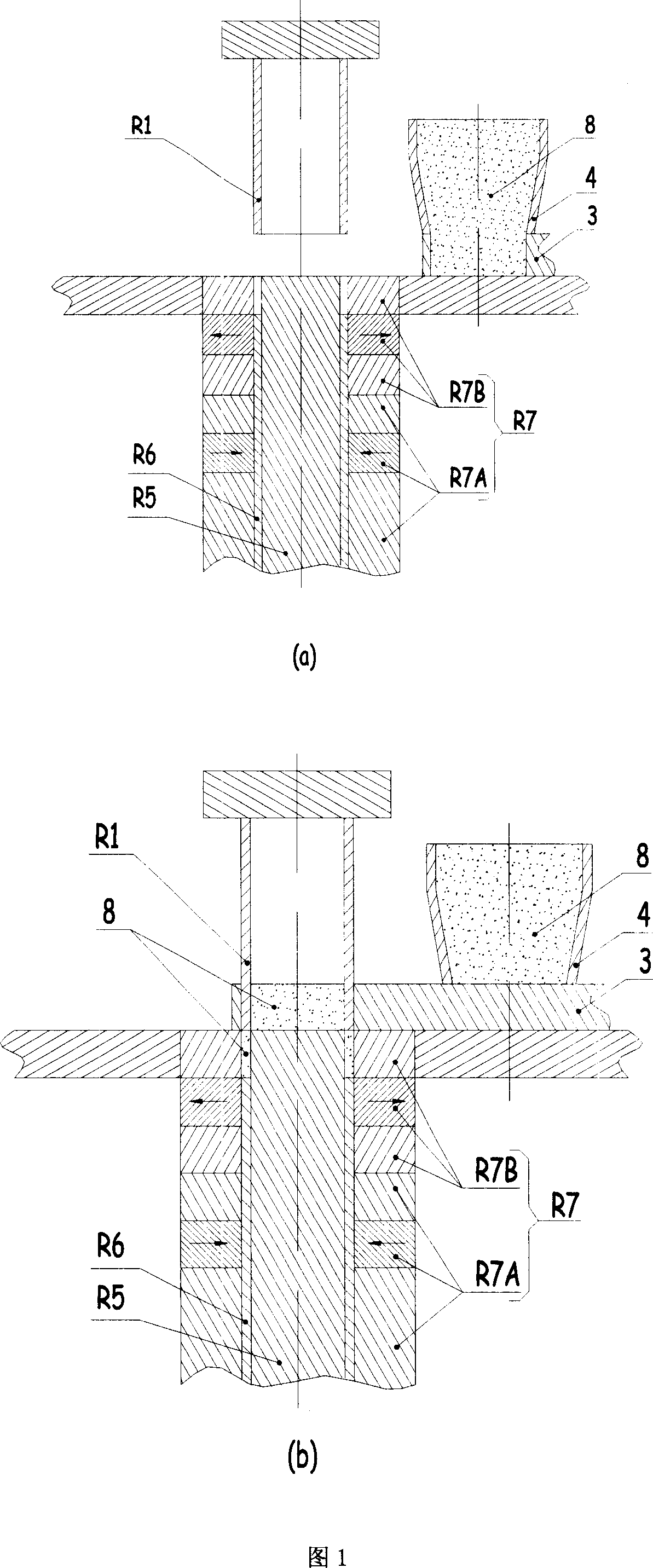
[0045] Example 1: Pressing a radiation-oriented magnetic ring with a height-to-diameter ratio of 1 Specific steps:
[0046] a. As shown in Figure 1(a), it is the state of preparation before the pressing of the radiation-oriented magnetic ring. The height difference between the lower plane of the upper indenter R1 and the upper plane of the female mold R7 is equal to the height of the material box 3. When the magnetic powder 8 starts to be pressed The density to be achieved will determine the height of the material box 3, the greater the required density, the higher the height of the material box 3; at this time, the height difference between the upper plane of the female mold R7 and the upper plane of the lower pressure head R6 is the first pressing The feeding height of the magnetic ring; the upper plane of the lower core rod R5 and the upper plane of the female mold R7 are at the same level, and the relative position remains unchanged during the entire pressing process.
[0...
example 2
[0059] Example 2: The specific steps of pressing a parallel orientation magnet:
[0060] l. The preparation state of the press before pressing the parallel orientation magnet is the same as when pressing the radiation orientation magnetic ring. The feeding process is as shown in Figure 6(a) parallel orientation magnet feeding, the density to be achieved when the magnetic powder 8 starts pressing will determine the height of the material box 3, the greater the required density, the higher the height of the material box 3. First, the material box 3 is moved to the top of the female mold P7; then, the upper pressing head P1 presses the magnetic powder 8 into the female mold P7 to realize feeding.
[0061] m, the pressing process of parallel orientation magnet P9 as shown in Figure 6 (b), at first, the upper pressure head P1 rises to the position of the ready state, and the material box 3 returns to the bottom of the material bin 4; then, the upper pressure head P1 goes down, Unt...
example 3
[0070] Example 3: Specific steps for pressing a vertically oriented magnet:
[0071] r. The preparation state of the press before pressing the vertically oriented magnet is the same as when pressing the radiation oriented magnetic ring. Feeding process As shown in Figure 9(a), the vertically oriented magnets are fed. The density to be achieved by the magnetic powder 8 at the beginning of pressing will determine the height of the material box 3. The greater the required density, the higher the height of the material box 3. First, the material box 3 is moved to the top of the female mold V7; then, the upper pressing head V1 presses the magnetic powder 8 into the female mold V7 to realize feeding.
[0072] s. As shown in Figure 9(b), the pressing process of the vertically oriented magnet V9, first, the upper pressing head V1 rises to the position of the ready state, and the material box 3 returns to the bottom of the material bin 4; then, the upper pressing head V1 moves downward...
PUM
 Abstract
Description
Claims
Application Information