Methods, apparatuses and systems for drainage
a technology of drainage apparatus and drainage tube, applied in the direction of stents, cannulas, intravenous devices, etc., can solve the problems of difficult to solve, difficult to apply unphyiological negative pressure, and difficult to achieve cardio-pulmonary bypass (snared venae cavae) , to achieve the effect of enhancing drainag
- Summary
- Abstract
- Description
- Claims
- Application Information
AI Technical Summary
Benefits of technology
Problems solved by technology
Method used
Image
Examples
example 1
annula Comparisons
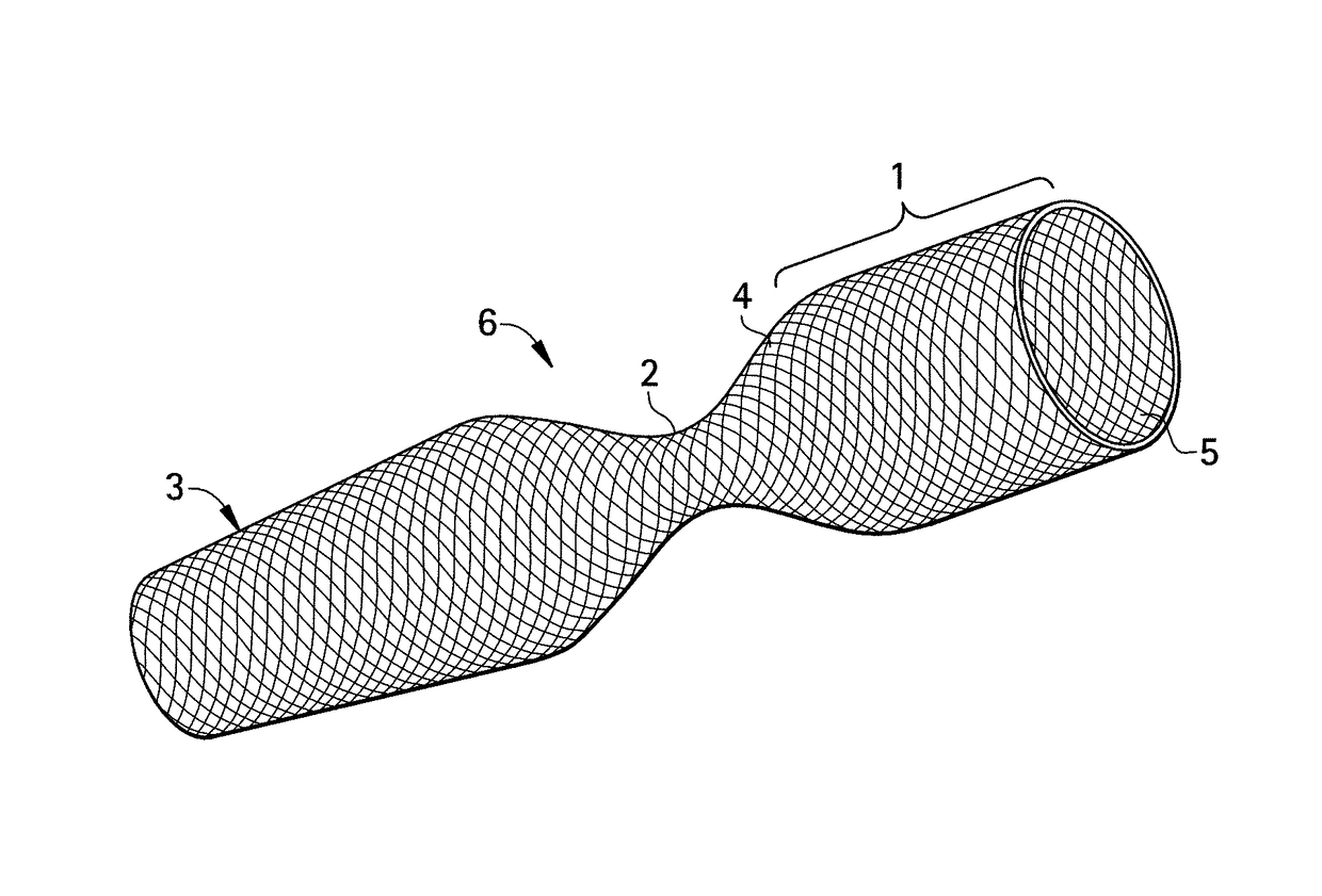
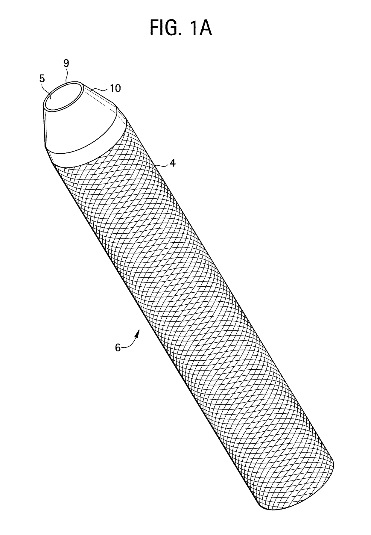
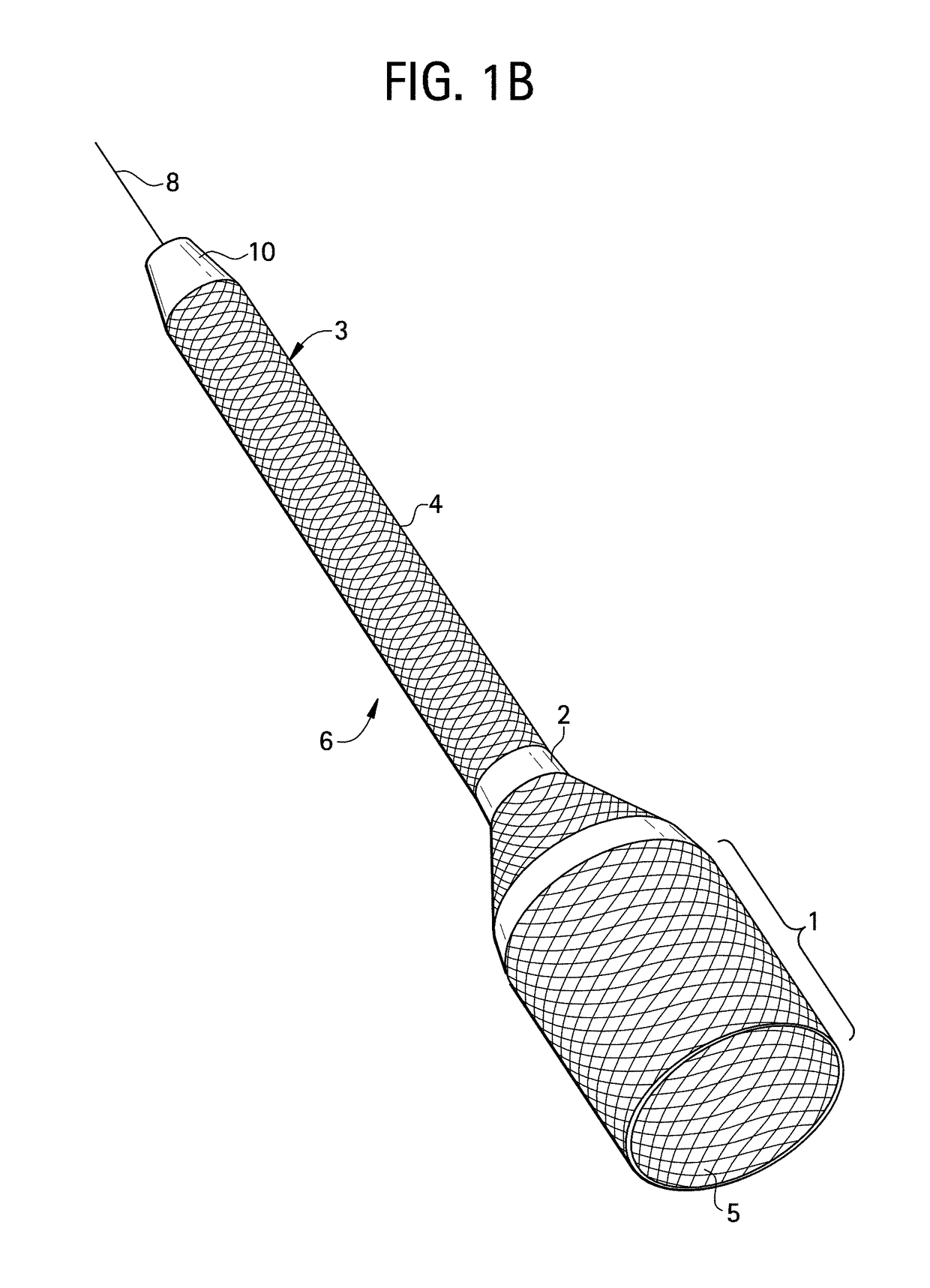
[0185]In vivo experiments in bovine were conducted to compare the flow rate of fluids through the high performance cannula 6 and other commercially available cannulas of various diameters. Specifically, the comparisons involved the cannulation of the superior vena cava (the target vessel) through the jugular vein (the access vessel) after calibration of the aperture (through which the cannula and blood flow have to pass) access to 28 French (9.33 mm), 24 French (8 mm), and 20 French (6.66 mm) cannulas. The cannulas tested included DLP cannulas (Medtronic), Biomedicus cannulas (Medtronic), generic chest tube cannulas, and the high performance cannulas. To insure standardized conditioning, gravity drainage was set at 60 cm of water for each of the cannulas tested.
[0186]The results of the comparisons are shown in Table 1.
[0187]
TABLE 1Comparison AComparison BComparison C28 French24 French20 French(9.33 mm)(8 mm)(6.66 mm)YSDNYSDNYSDNDLP cannulas4.1170.07633.3170.07631.7...
example 2
gh Performance Cannulas
[0190]In order to prepare the high performance cannula 6 for use, a mandrel 7 (as shown, for example, in FIG. 3A) is introduced into the cannula 6. Next the cannula 6 is stretched over the mandrel 7 in order to reduce its diameter. Once the cannula 6 is fully in its low profile conformation, it will have a minimal outer diameter.
[0191]The vessel to be cannulated is then punctured with the sharp hollow needle. A J-tip guidewire 8 is then introduced into the vessel. Proper positioning of the guidewire is checked by ultrasound, fluoroscopy, or any other suitable means. While keeping the guidewire in place in situ, the needle is then removed from the vessel.
[0192]To achieve vessel orifice (e.g., access aperture) dilation, a small (e.g., No. 1) dilator is placed over the guidewire 8 and then removed, while the guidewire 8 remains in place. The access aperture can be redilated using an intermediate (No. 2) dilator that is inserted and removed. Finally, the largest d...
example 3
re of High Performance Cannulas
[0196]The manufacture of the high performance cannulas may include some or all of the following steps: (a) defining the diameter and length needed; (b) selecting the appropriate materials; (c) preparing the cannula 6; (d) preparing the mandrel 7; and (e) preparing a locking mechanism 12. Additionally, those skilled in the relevant arts will recognize that the high performance cannulas may also be made by any other methods or processes known in the art.
[0197]A variety of parameters influence and define the optimal diameter and length configuration of the high performance cannulas. These parameters include target flow, target vessel diameter, target vessel length, target vessel access diameter, target vessel access length, desired covered cannula 6 length proximal to the point of insertion, and / or the desired connector. In one embodiment the cannula 6 can be approximately ⅜″ in diameter and 50-70 cm in length, depending on the particular application. Det...
PUM
 Abstract
Description
Claims
Application Information
 - R&D
- Intellectual Property
- Life Sciences
- Materials
- Tech Scout
- Unparalleled Data Quality
- Higher Quality Content
- 60% Fewer Hallucinations
Browse by: Latest US Patents, China's latest patents, Technical Efficacy Thesaurus, Application Domain, Technology Topic, Popular Technical Reports.
© 2025 PatSnap. All rights reserved.Legal|Privacy policy|Modern Slavery Act Transparency Statement|Sitemap|About US| Contact US: help@patsnap.com


