Waveguide device and antenna device including the waveguide device

a waveguide and antenna technology, applied in the direction of slot antennas, antennas, electrically long antennas, etc., can solve the problems of propagation loss in signals, unwanted reflection of propagating electromagnetic waves, and inducing unwanted noises, so as to improve the degree of impedance matching

Active Publication Date: 2018-07-17
WGR CO LTD +1
View PDF26 Cites 32 Cited by
  • Summary
  • Abstract
  • Description
  • Claims
  • Application Information

AI Technical Summary

Benefits of technology

[0013]Non-Patent Document 1 discloses varying the height of the ridge at a position near a bend or a branching portion in order to enhance impedance matching at the bend or the branching portion. In a waveguide which is disclosed in Non-Patent Document 2, the ridge width varies at a portion near a branching portion of the waveguide member.
[0014]Various embodiments of the present disclosure provide a waveguide device with an enhanced degree of impedance matching at a bend or a branching portion of a waveguide member.
[0017]In accordance with an embodiment of the present disclosure, a novel construction for rods that constitute an artificial magnetic conductor can enhance the degree of impedance matching at any bend or branching portion of a waveguide member.

Problems solved by technology

At such a portion of change in the direction that the waveguide member extends, unless remedied, an impedance mismatching would occur, thus causing unwanted reflection of a propagating electromagnetic wave.
Such reflection would not only cause a propagation loss in the signal, but also induce unwanted noises.

Method used


Image

  • Waveguide device and antenna device including the waveguide device
  • Waveguide device and antenna device including the waveguide device
  • Waveguide device and antenna device including the waveguide device

Examples


application example

SECOND VARIANT OF APPLICATION EXAMPLE

[0287]The radar system 510 is able to detect a target by using a continuous wave(s) CW of one or plural frequencies. This method is especially useful in an environment where a multitude of reflected waves impinge on the radar system 510 from still objects in the surroundings, e.g., when the vehicle is in a tunnel.

[0288]The radar system 510 has an antenna array for reception purposes, including five channels of independent reception elements. In such a radar system, the azimuth-of-arrival estimation for incident reflected waves is only possible if there are four or fewer reflected waves that are simultaneously incident. In an FMCW-type radar, the number of reflected waves to be simultaneously subjected to an azimuth-of-arrival estimation can be reduced by exclusively selecting reflected waves from a specific distance. However, in an environment where a large number of still objects exist in the surroundings, e.g., in a tunnel, it is as if there we...


PUM


Abstract

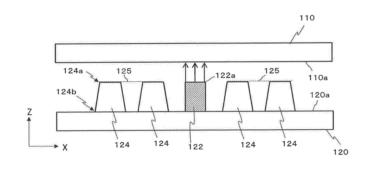
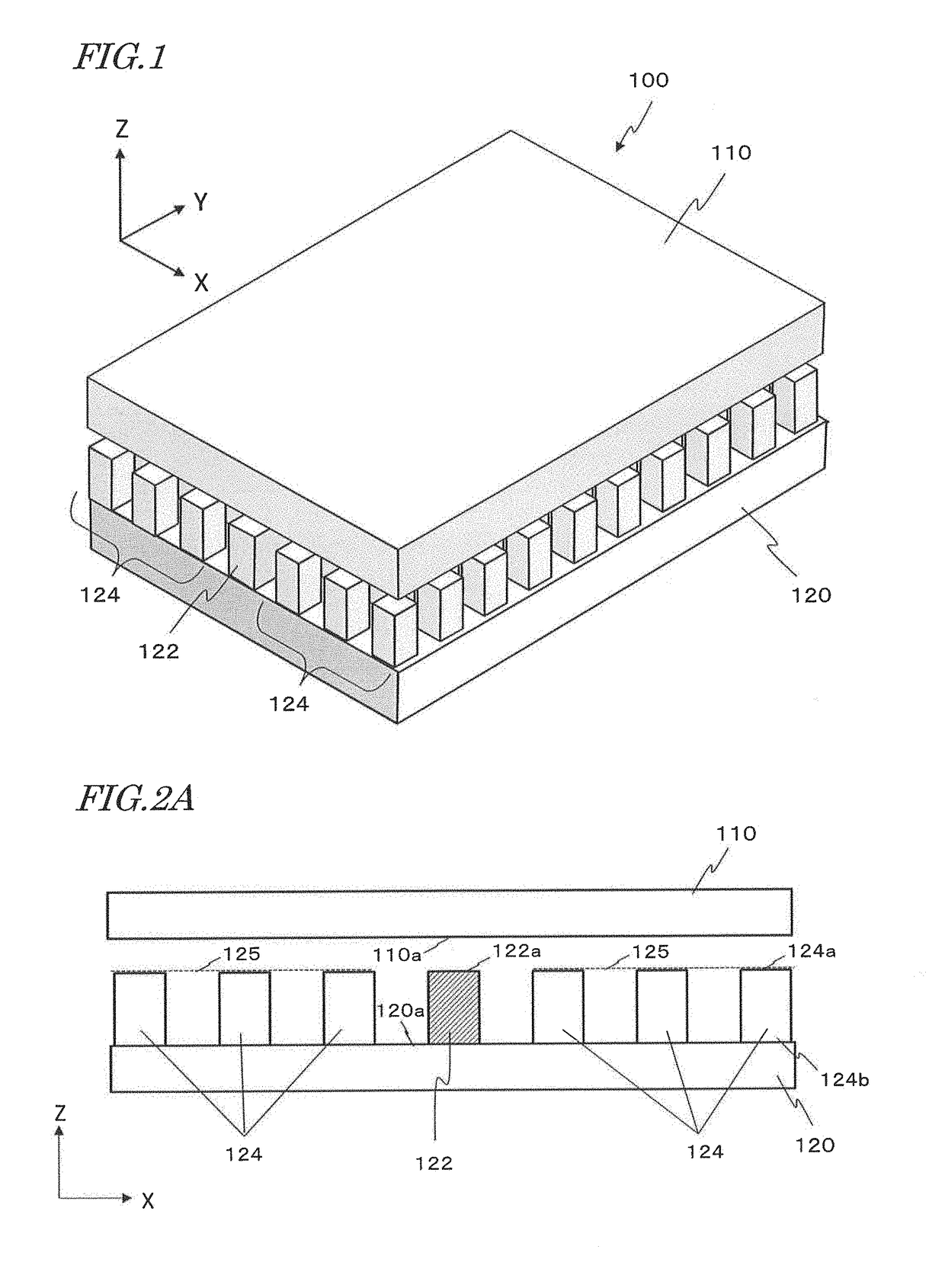
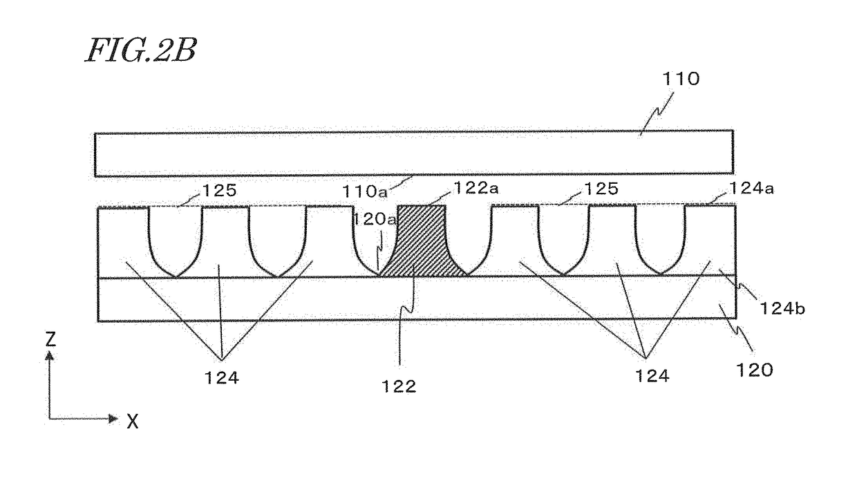
A waveguide device includes: a first conductive member having an electrically conductive surface; a second conductive member having a plurality of electrically conductive rods arrayed thereon, each conductive rod having a leading end opposing the conductive surface; and a waveguide member having an electrically conductive waveguide face opposing the conductive surface, the waveguide member being disposed among the conductive rods and extending along the conductive surface. The waveguide member includes at least one of a bend and a branching portion. A measure of an outer shape of a cross section of at least one of the plurality of conductive rods that is adjacent to the bend or the branching portion, taken perpendicular to an axial direction of the at least one conductive rod, monotonically decreases from a root that is in contact with the second conductive member toward a leading end.

Description

BACKGROUND[0001]1. Technical Field:[0002]The present disclosure relates to a waveguide device, and an antenna device including the waveguide device.[0003]2. Description of the Related Art:[0004]Examples of waveguiding structures including an artificial magnetic conductor are disclosed in Patent Documents 1 to 3 and Non-Patent Documents 1 and 2 as follows.[0005]Patent Document 1: International Publication No. 2010 / 050122[0006]Patent Document 2: the specification of U.S. Pat. No. 8,803,638[0007]Patent Document 3: the specification of European Patent Application Publication No. 1331688[0008]Non-Patent Document 1: H. Kirino and K. Ogawa, “A 76 GHz Multi-Layered Phased Array Antenna using a Non-Metal Contact Metamaterial Waveguide”, IEEE Transaction on Antenna and Propagation, Vol. 60, No. 2, pp. 840-853, February, 2012[0009]Non-Patent Document 2: A. Uz. Zaman and P.-S. Kildal, “Ku Band Linear Slot-Array in Ridge Gapwaveguide Technology, EUCAP 2013, 7th European Conference on Antenna and...

Claims


Application Information

Patent Timeline
Patent Type & Authority Patents(United States)
IPC IPC(8): H01P3/00H01Q11/14H01Q21/00H01Q21/06H01Q13/16
CPCH01Q13/16H01P3/00H01Q21/064H01Q21/0006H01Q11/14
Inventor KIRINO, HIDEKIKAMO, HIROYUKI
Owner WGR CO LTD
Why Eureka
Try Eureka