Optomechanical force sensors, cantilevers, and systems thereof

a technology of force sensors and cantilevers, applied in the field of optomechanical force sensors, can solve the problems of large shifts in the resonant frequency of the system, optical sensitivity will decrease, and the mass cannot be decreased indefinitely, so as to reduce the time required to measure large areas, enhance the sensitivity to mechanical deflection, and enhance the dynamic range

Active Publication Date: 2018-07-24
NAT TECH & ENG SOLUTIONS OF SANDIA LLC
View PDF19 Cites 22 Cited by
  • Summary
  • Abstract
  • Description
  • Claims
  • Application Information

AI Technical Summary

Benefits of technology

[0007]Although no particular mechanism is to be viewed as limiting, we note that the disclosed system can allow for increased optical readout sensitivity of mechanical forces experienced by a probe when the probe is of a sub-wavelength dimensional scale.
[0008]That is, it is well known for the probes of scanning force microscopes to be mounted on cantilever beams. Sensitivity is enhanced by decreasing the mass of the cantilever probe. However, the mass cannot be decreased indefinitely. Instead, a lower bound on the mass is imposed because a laser beam (used to read the position of the probe) cannot be focused to a point, but only at best to a diffraction-limited spot. Hence once the probe drops to below the size of the diffraction-limited spot, only a fraction of the incident laser light will be intercepted and reflected toward a detector. Consequently, as mechanical sensitivity increases, optical sensitivity will decrease, and a limiting tradeoff will eventually be reached.
[0010]Implementations of our new optical topographic probe incorporate an optomechanically coupled system comprising a cantilevered, high-Q optical cavity suspended from a microchip. A single-mode optical waveguide can direct the light within and into and out of the optical cavity. This combination of features permits the use of a sub-wavelength probe without the penalty suffered by reflective probes in conventional ATMs. Concurrently, this combination of features can enhance the sensitivity to mechanical deflection enough to permit the stiffening of the cantilever to achieve enhanced dynamic range.
[0011]Still further, the high-Q optical cavity in our system can be probed, in implementations, using on-chip optical waveguides. This allows the system to be wavelength multiplexed, so that a plurality of waveguide-fed cavities all use slightly different wavelengths of light. This, in turn, allows for a multiplexer / demultiplexer (MUX / DEMUX) architecture using wavelength-division multiplexing (WDM) or dense wavelength-division multiplexing (DWDM) that can massively parallelize the topographic measurement of a system under test. Among other advantages, this can reduce the time required to measure large areas.Definitions

Problems solved by technology

Even slight perturbations or deformations in the optical cavity can lead to large shifts of the resonant frequency of the system.
However, the mass cannot be decreased indefinitely.
Consequently, as mechanical sensitivity increases, optical sensitivity will decrease, and a limiting tradeoff will eventually be reached.

Method used


Image

  • Optomechanical force sensors, cantilevers, and systems thereof
  • Optomechanical force sensors, cantilevers, and systems thereof
  • Optomechanical force sensors, cantilevers, and systems thereof

Examples


example 1

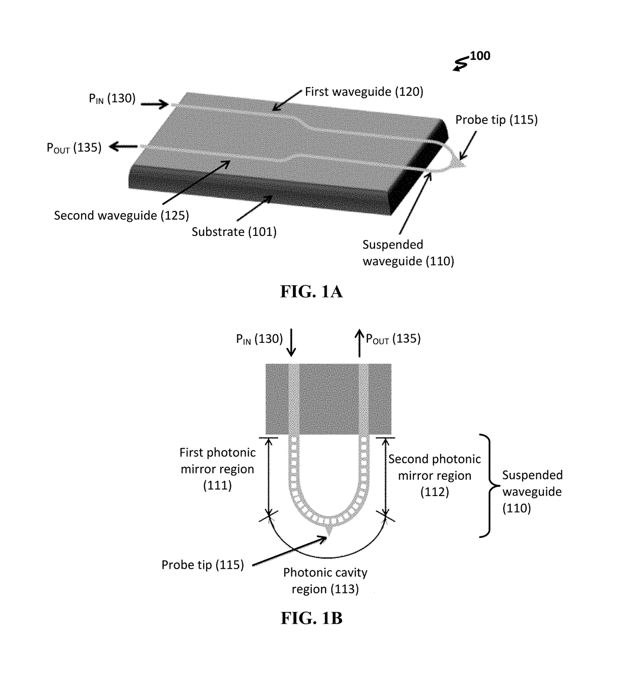
[0081]A single-mode waveguide is defined on the device layer of a silicon-on-insulator (SOI) substrate. With reference to FIG. 1A, the silicon waveguide-based device 100 delivers a power input PIN from a coupled, external light source to the suspended waveguide 110.

[0082]The use of on-chip waveguides on SOI allows for easy integration with standard v-groove couplers, enabling robust, precise alignment into and out of the device, regardless of device orientation, i.e., vertical or horizontal orientation.

[0083]Where the single-mode waveguide approaches the end of the SOI chip, a photonic crystal is defined on the section of waveguide that is freestanding over the edge of the SOI (FIG. 1B). This photonic crystal has two identified regions: a cavity region 113 that is located in closest proximity to the location of the probe tip 115, and bordering the cavity region on either side, a pair of mirror regions 111, 112. The nature of the overhanging photonic crystal allows for unrestricted m...

example 2

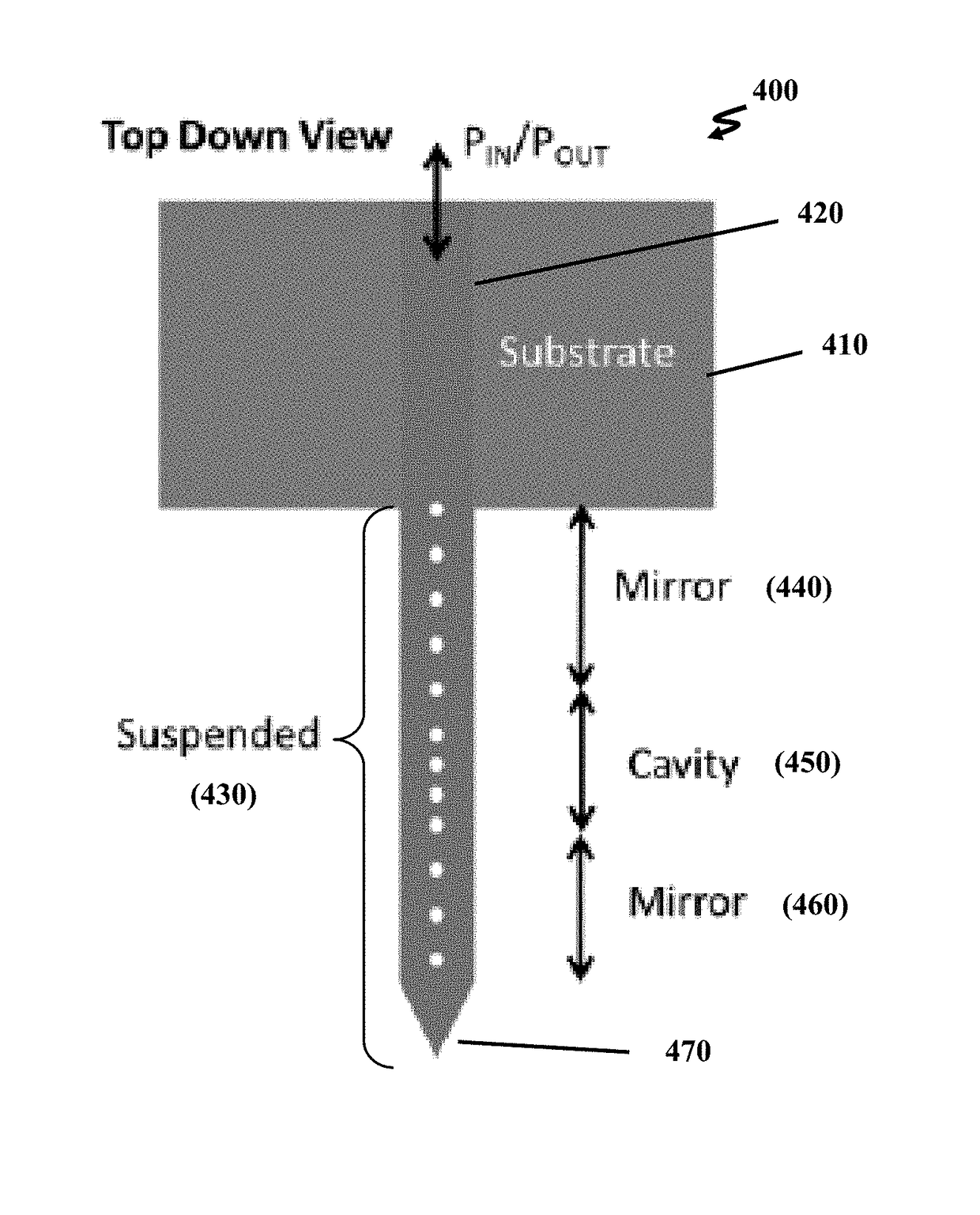
[0096]With reference to FIG. 4, an alternative design concept 400 places the optical cavity within a single rectilinear cantilevered beam instead of within a half-loop. This decreases the number of attachment points where the cantilevered beam is anchored to the substrate, and it invites the application of standard cantilevered beam fabrication techniques. As a consequence, the complexity of the design is reduced, simplifying both the fabrication and the integration of the optomechanical sensor device.

[0097]As seen in the figure, the cantilever structure includes substrate 410, input-output waveguide 420 formed on substrate 410, and suspended waveguide 430 conformed as a cantilevered beam, such as a rectangular beam, that extends rectilinearly from the substrate and has a single anchor. Waveguide 420 is a bidirectional waveguide having a single end for the injection of input light and the emission of output light.

[0098]Suspended waveguide 430 contains mirror region 440, optical cavi...


PUM


Abstract

An optomechanical force sensor includes a substrate, a cantilevered beam anchored to the substrate, and a probe tip positioned near an end of the cantilevered beam distal to the substrate. A suspended waveguide is disposed on the cantilevered beam and is optically continuous with an input / output waveguiding structure. An optical cavity is defined within the suspended waveguide.

Description

CROSS-REFERENCE TO RELATED APPLICATION[0001]This application claims priority to U.S. Provisional Patent Application No. 62 / 267,972, filed on Dec. 16, 2015 under the title, “OPTOMECHANICAL FORCE SENSORS, CANTILEVERS, AND SYSTEMS THEREOF,” the entirety of which is incorporated herein by reference.STATEMENT OF GOVERNMENT INTEREST[0002]This invention was made with Government support under contract no. DE-AC04-94AL85000 awarded by the U.S. Department of Energy to Sandia Corporation. The Government has certain rights in the invention.FIELD OF THE INVENTION[0003]The present invention relates to optomechanical force sensors including a suspended waveguide. In some instances, such sensors can be configured to optically detect a change in force exerted on a probe tip (e.g., arising from a change in surface topography of a sample). Systems including such sensors are also described herein.BACKGROUND OF THE INVENTION[0004]As nanoscale fabrication and research progress, it becomes increasingly ne...

Claims


Application Information

Patent Timeline
Patent Type & Authority Patents(United States)
IPC IPC(8): G01Q60/38
CPCG01Q60/38B82Y15/00B82Y20/00G01Q20/02G01Q20/04G02B1/005G02B6/1225G02B2006/12138
Inventor DOUGLAS, ERICA ANNEICHENFIELD, MATTJONES, ADAMCAMACHO, RYANHENRY, MICHAEL DAVIDDOUGLAS, JAMES KENNETH
Owner NAT TECH & ENG SOLUTIONS OF SANDIA LLC
Why Eureka
Try Eureka