Axial fan for industrial use

a technology for axial fans and industrial applications, applied in the direction of machines/engines, non-positive displacement fluid engines, liquid fuel engine components, etc., can solve the problems of reducing the efficiency of pitch angles and/or lower speeds, reducing the efficiency of blades designed to have high efficiency at low pitch angles and at low speeds, and reducing turbulence. , the effect of improving the aerodynamic efficiency of the blades

Active Publication Date: 2018-07-31
COFIMCO
View PDF31 Cites 5 Cited by
  • Summary
  • Abstract
  • Description
  • Claims
  • Application Information

AI Technical Summary

Benefits of technology

[0012]Purpose of the present invention is therefore to provide an axial fan which allows to overcome the limitations described above and, in particular, allows to obtain high efficiency over a wide range of pitch angles, incidence angles and peripheral speed of the blades.
[0015]The fluid passage thus created produces effects especially in the most critical portion of the blade, where the lapping flow tends to detach from the blade surface. The configuration of the blade is therefore particularly effective.
[0016]The secondary blade portion, which acts as a flap for the principal blade portion and defines the fluid passage, allows to improve the overall performance of the fan. In particular, the fluid passage is traversed by a fluid flow which causes a depression at the outlet of the fluid channel itself. In turn, the vacuum draws the lapping flow towards the blade surface and counteracts the detachment tendency which normally occurs over a speed threshold. The fan blades according to the invention may thus operate correctly even for speed and / or incidence angles that would cause stalling of blades of equal size, however, devoid of the fluid passage defined by the flap between intrados and extrados. The aerodynamic efficiency of the blade is at the same time improved by the general reduction of turbulence at the trailing edge.

Problems solved by technology

The vortices cause a loss of lift and, consequently, a decline of the fan efficiency.
To this improvement, however, corresponds a reduced efficiency for pitch angles and / or lower speeds.
Conversely, blades designed to have high efficiency at low pitch angles and at low speeds are totally unsatisfactory for higher angles and speeds, both for the low efficiency, and for greater ease to stall.
The difficulty of achieving satisfactory performance in a wider range of operating conditions is largely dependent on the separate peculiarities of axial fans for industrial use, particularly on the large size.
A blade of said axial fans, in fact, measuring several meters in the radial direction, and therefore the speed difference between the distal end and the proximal end is very high, enough to bring the peripheral portions of the blades to stall conditions while the radially innermost portions still have a relatively abundant margin, but that cannot be exploited.

Method used


Image

  • Axial fan for industrial use
  • Axial fan for industrial use
  • Axial fan for industrial use

Examples


Embodiment Construction

[0027]The invention described below is particularly suited for implementing axial fans of large dimensions, for example for heat exchangers used in plants for the liquefaction of natural gas, refineries or plants for the production of electricity in a combined cycle or with a steam turbine. In particular, the axial fans for industrial use have a diameter up to about 12 meters and rotation regimes that involve peripheral speeds of the blades up to about 75 m / s. Furthermore, for typical applications of axial industrial fans we must assume that the Reynolds number of the fluid processed, namely air, is greater than 10000.

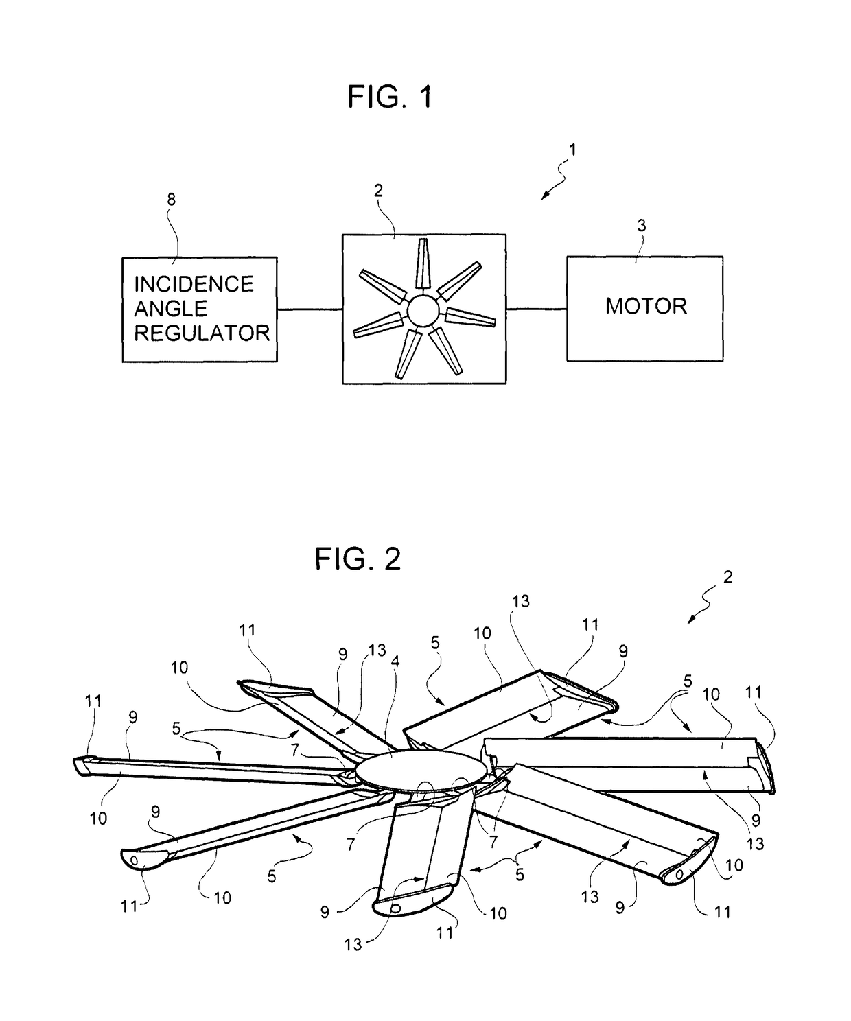
[0028]With reference to FIG. 1, a fan assembly, indicated in its entirety with the number 1, comprises an axial fan 2 driven by an electric motor 3.

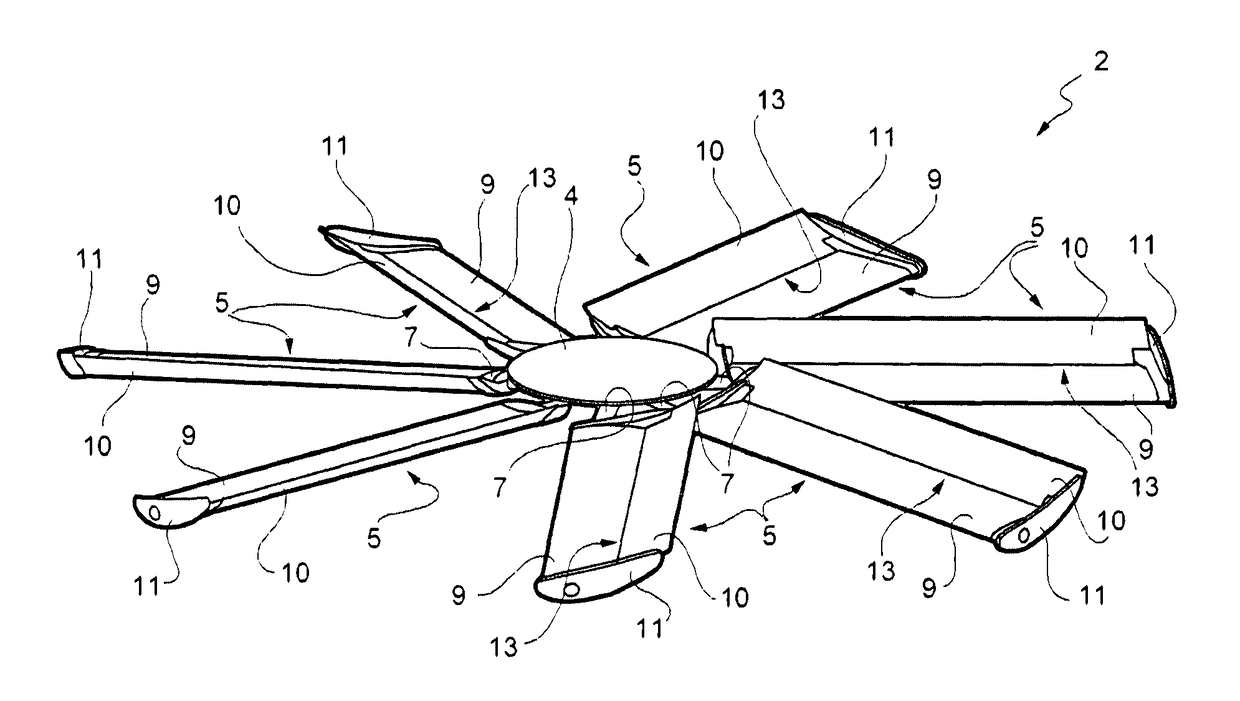
[0029]The axial fan 2, which is represented in more detail in FIG. 2, comprises a hub 4, connected to a shaft of the electric motor 3, and a plurality of blades 5 which extend from the hub 4 substantially in the radial dire...


PUM


Abstract

An axial fan comprises a hub and a plurality of blades extending from the hub; wherein each blade comprises a main blade portion and a secondary blade portion and the secondary blade portion has a leading edge adjacent to a leading edge of the main blade portion and forms a flap for the main blade portion; wherein a fluid passage is defined between the leading edge of the main blade portion and the leading edge of the secondary blade portion; wherein the main blade portion has a main chord and the secondary blade portion has a secondary chord; and wherein the main chord and the secondary chord form a relative attack angle comprised between 5° and 35°.

Description

TECHNICAL FIELD[0001]The present invention relates to an axial fan for industrial use.BACKGROUND ART[0002]As known, an axial fan generally comprises a hub and a plurality of blades which extend substantially in a radial direction from the hub.[0003]The hub is rotatable about an axis and is connected to an electric motor for receiving a rotary motion by way of a transmission system.[0004]The blades are provided with an airfoil, so that the rotation effect imparted by the motor, generates a pressure difference between the extrados and intrados of the blades. In turn, the pressure difference produces an air flow in a direction substantially parallel to the hub axis.[0005]The air flow rate provided in axial motion depends on various factors, comprising mainly the rotation speed, the shape of the airfoil and the pitch angle of the blades.[0006]It is known that, given a certain rotation speed, the incidence angle (i.e. the angle between the velocity vector of the air and the chord of the ...

Claims


Application Information

Patent Timeline
Patent Type & Authority Patents(United States)
IPC IPC(8): F04D29/38F04D29/68F04D19/00
CPCF04D29/681F04D29/388F04D29/384F04D19/002F04D29/684F04D29/682
Inventor GALLINA, CARLO
Owner COFIMCO
Why Eureka
Try Eureka