Common mode filter

a filter and common mode technology, applied in the direction of fixed inductances, basic electric elements, inductances, etc., can solve the problem of likely failure of its own circuit, and achieve the effect of reducing the frequency of the common mode nois

Active Publication Date: 2018-07-31
ELMEC
View PDF14 Cites 1 Cited by
  • Summary
  • Abstract
  • Description
  • Claims
  • Application Information

AI Technical Summary

Benefits of technology

[0050]In the common mode filter according to claim 1 of the present invention, the first and second single coils serially inserted and connected to the differential signal line, are spirally formed in the dielectric layer of a multilayer structure so as to be superimposed on each other in the thickness direction, and the first control coil is spirally formed in the dielectric layer so as to be sandwiched between these first and second signal coils interposing the dielectric layer, and the first embedded resistor is disposed in the dielectric layer so as to be connected to at least one of the outer peripheral end or the inner peripheral end of the first control coil, thus forming the first feedback loop circuit via these first control coil and first embedded resistor. Therefore, in the configuration including the first and second signal coils and the first control coil, the magnetic coupling between the first and second signal coils can be controlled by the first control coil, and the reflection of a common mode noise can be suppressed, and the common mode noise of 2 GHz or less can be sufficiently removed.
[0051]In the common mode filter according to claim 2 of the present invention, the first feedback loop circuit is formed in the dielectric layer by the first control coil and the first embedded resistor. Therefore, an external connecting configuration can be simplified.
[0052]In the common mode filter according to claim 3 of the present invention, the outer peripheral end and the inner peripheral end of the first control coil are connected to the first and second external terminals directly or via the first embedded resistor, the first and second external terminals being connected to the external feedback circuit for forming the first feedback loop circuit, thus forming the first feedback loop circuit via these first and second external terminals. Therefore, the magnetic coupling between the first and second signal coils is controlled over a wider range via the external first feedback loop circuit, and the reflection of the common mode noise can be suppressed, and the common mode noise of 2 GHz or less can be removed.
[0053]In the common mode filter according to claim 4 of the present invention, the first and second signal coils serially inserted and connected to the differential signal line, are spirally formed in the dielectric layer of a multilayer structure so as to be superimposed on each other in the thickness direction, and the second control coil is spirally formed in the dielectric layer so as to face the first signal coil interposing the dielectric layer, and the third control coil is spirally formed in the dielectric layer so as to face the second signal coil interposing the dielectric layer, thus forming the second and third feedback loop circuits via the second and third control coils and the second and the third embedded resistors. Therefore, according to such a configuration including the first and second signal coils and the second and third control coils, the magnetic coupling between the first and second signal coils is controlled by the second and third control coils, and the reflection of the common mode noise is suppressed, and the common mode noise of 2 GHz or less can be removed, in a state in which an excellent magnetic coupling is maintained between the first and second signal coils.
[0054]In the common mode filter according to claim 5 of the present invention, the second and third feedback loop circuits are formed in the dielectric layer via these second and third control coils and the second and third embedded resistors. Therefore, an external connecting configuration is simplified.
[0055]In the common mode filter according to claim 6 of the present invention, the outer peripheral end and the inner peripheral end of the second and third control coils are connected to the second and third external terminals directly or via the second and third embedded resistors, the second and third external terminals being connected to the external feedback circuit for forming the second and third feedback loop circuit, thus forming the second and third feedback loop circuit via these second and third external terminals. Therefore, the magnetic coupling between the first and second signal coils is controlled over a wider range via the external second and third feedback loop circuits, and the reflection of the common mode noise can be suppressed, and the common mode noise of 2 GHz or less can be removed.

Problems solved by technology

However, in a device for transmitting an ultra-high-speed differential signal of the GHz band, the transmission line is likely to be the antenna pattern, and therefore malfunction of its own circuit is likely to occur due to a radiation noise generated from its own circuit pattern.

Method used


Image

  • Common mode filter
  • Common mode filter
  • Common mode filter

Examples


Embodiment Construction

[0077]Embodiments of the present invention will be described hereafter, with reference to the drawings.

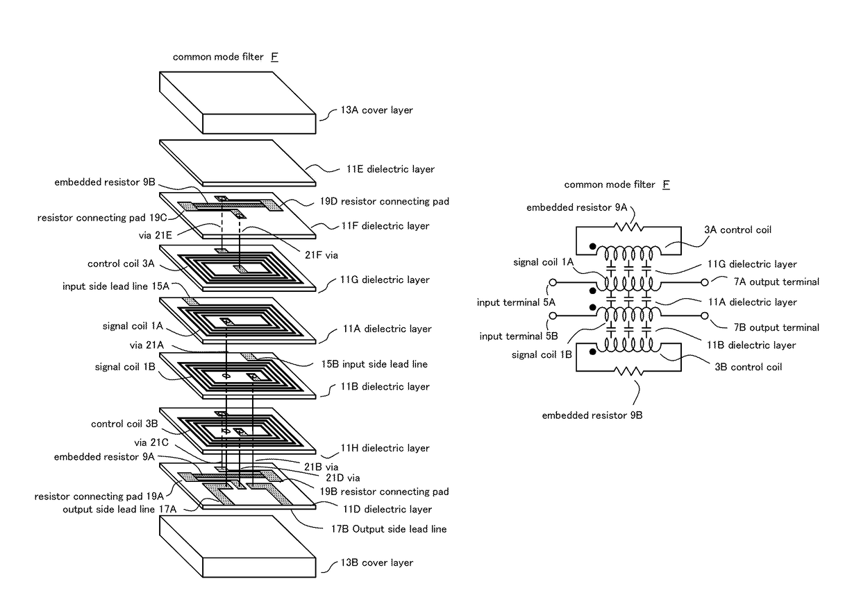
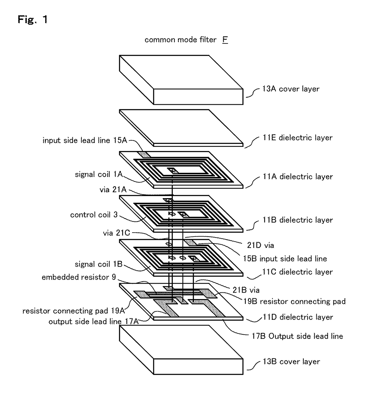
[0078]FIG. 1 is an exploded perspective view showing a basic configuration of a common mod filter F according to the present invention.

[0079]A signal coil (first signal coil) 1A is formed in a dielectric layer 11A, a signal coil (second signal coil) 1B is formed in a dielectric layer 11C, and a control coil (first control coil) 3 is formed in a dielectric layer 11B, respectively.

[0080]These dielectric layers 11A to 11C are composed of a publicly-known laminated ceramic or a multilayer resin substrate having substantially the same shape such as a rectangular thin plate, and are laminated so as to sandwich the dielectric layer 11B between the dielectric layer 11A and the dielectric layer 11C.

[0081]These signal coils 1A, 1B, and control coil 3 are made of a publicly-known conductive material and spirally formed on one surface of each layer of the dielectric layers 11A to 11C by thin f...


PUM

PropertyMeasurementUnit
frequencyaaaaaaaaaa
frequencyaaaaaaaaaa
frequencyaaaaaaaaaa

Abstract

A common mode filter suppressing a reflection of a common mode noise and sufficiently removing the common mode noise of 2 GHz or less includes: a signal coil spirally formed in a dielectric layer of a multilayer structure, and serially inserted and connected to one of the differential signal lines; a signal coil inserted and connected to the other differential signal line and formed in the dielectric layer so as to face the signal coil through the dielectric layer; a control coil formed in the dielectric layer so as to be sandwiched between the first and second signal coils interposing the dielectric layer and wound in the same direction as the signal coil; and an embedded resistor connected to at least one of an outer peripheral end or an inner peripheral end of the control coil, thus forming a feedback loop circuit by the control coil and the embedded resistor.

Description

TECHNICAL FIELD[0001]The present invention relates to a common mode filter, and particularly to a new common mode filter capable of suppressing a reflection of a common mode noise and adjusting a common mode removing characteristic.DESCRIPTION OF RELATED ART[0002]Conventionally, a common mode choke coil is generally used as an electronic component for removing a common mode noise on a transmission line for an ultra-high-speed differential signal.[0003]Although the conventional common mode choke coil hardly allows an ultra-high-speed differential signal of a GHz band to pass under an influence of a magnetic loss of a magnetic material, the common mode choke coil realizing 10 GHz or more pass band for the differential signal has been commercialized.[0004]The principle of removing the common mode noise of the common mode choke coil is as follows: a high series impedance is formed for a common mode signal by utilizing magnetic coupling, and the common mode noise is reflected to an input...

Claims


Application Information

Patent Timeline
Patent Type & Authority Patents(United States)
IPC IPC(8): H03H7/06H03H7/42H01F27/28H01F27/40H03H1/00
CPCH03H7/427H01F27/2804H03H7/06H01F27/40H03H2001/0085H01F17/00H03H7/09H01F17/0013H01F2017/0093
Inventor KAMEYA, MASAAKI
Owner ELMEC
Why Eureka
Try Eureka