High temperature avionic line replaceable units and aircraft systems containing the same

a technology of replaceable units and avionic lines, applied in the field of aircraft, can solve problems such as avionic lru failure, avionic lru failure stem, and unplanned maintenance events, and achieve the effect of increasing temperature toleran

Active Publication Date: 2018-08-07
HONEYWELL INT INC
View PDF13 Cites 13 Cited by
  • Summary
  • Abstract
  • Description
  • Claims
  • Application Information

AI Technical Summary

Benefits of technology

[0023]Avionic LRUs having increased temperature tolerances and other desirable properties are provided. Embodiments of the avionic LRU are removably mountable or attachable to an avionic LRU receptacle, which includes a receptacle connector interface having a receptacle terminal array. In one embodiment, the avionic LRU includes at least one microelectronic device and an LRU housing, which contains an enclosed cavity in which the microelectronic device is located. The LRU housing further includes an electrically-routed housing wall, such as ceramic substrate on which or in which electrically-conductive interconnect features are formed. The electrically-routed housing wall has an inner principal surface or frontside, which partially bounds the enclosed cavity and to which the microelectronic device is bonded. The avionic LRU further includes a first LRU connector interface containing a first LRU terminal array. The first LRU terminal array is electrically coupled to the microelectronic device through the electrically-routed housing wall and projects from the LRU housing, possibly extending from the electrically-routed housing wall in a direction substantially opposite the microelectronic device. The LRU connector interface is configured to matingly engage the receptacle connector interface when the LRU is removably mounted to the avionic LRU receptacle such that corresponding terminals of the receptacle terminal array and the first LRU terminal array are placed in (e.g., electrical) communication.
[0024]In another embodiment, the avionic LRU includes a microelectronic device, an LRU housing enclosing a hermetically-sealed cavity in which the microelectronic device is located, and an LRU connector interface projecting from the LRU housing and having a LRU terminal array electrically coupled to the microelectronic device. A ceramic carrier contains electrical routing features, which electrically couple the microelectronic device to the LRU terminal array. The ceramic carrier forms a wall of the LRU housing and, in so doing, partially bounds the hermetically-sealed cavity to help preserve th

Problems solved by technology

An unplanned maintenance event may occur when, for example, an aircraft engine fails to start or responds sluggishly during MES.
Avionic LRU failures occur for a variety of reasons.
In many cases, avionic LRU failures stem from structural compromise of electrical interconnections between the electrically-active components of the LRU, such as the LRU connector terminals and the microelectronic devices housed within the LRU.
Such interconnection failures are often solder-related and may occur due to solder migration or crack formation in the presence of the elevated temperatures, repeated thermal cycling, and high vibratory loads typical of the avionic environment.
In certain instances, high temperature solders can be utilized to help mitigate such LRU failure modes, but oft

Method used


Image

  • High temperature avionic line replaceable units and aircraft systems containing the same
  • High temperature avionic line replaceable units and aircraft systems containing the same
  • High temperature avionic line replaceable units and aircraft systems containing the same

Examples


Embodiment Construction

[0033]The following Detailed Description is merely exemplary in nature and is not intended to limit the invention or the application and uses of the invention. Furthermore, there is no intention to be bound by any theory presented in the preceding Background or the following Detailed Description. The term “exemplary,” as appearing throughout this document, is synonymous with the term “example” and is utilized repeatedly below to emphasize that the following description provides only multiple non-limiting examples of the invention and should not be construed to restrict the scope of the invention, as set-out in the Claims, in any respect.

[0034]Overview

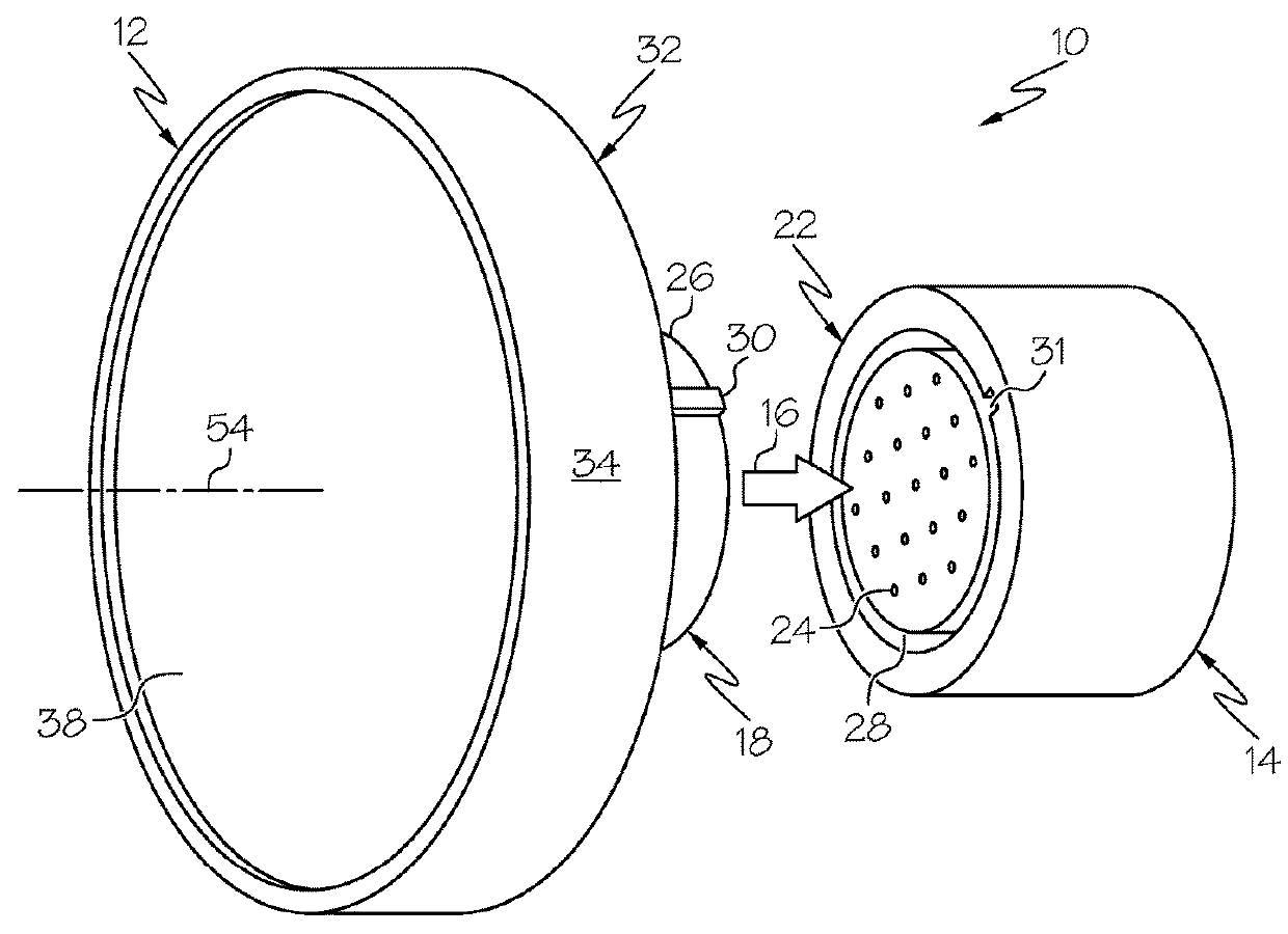
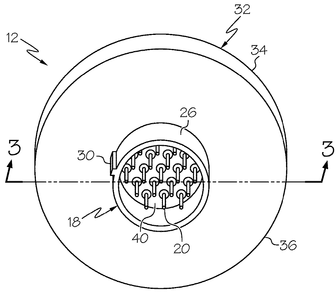
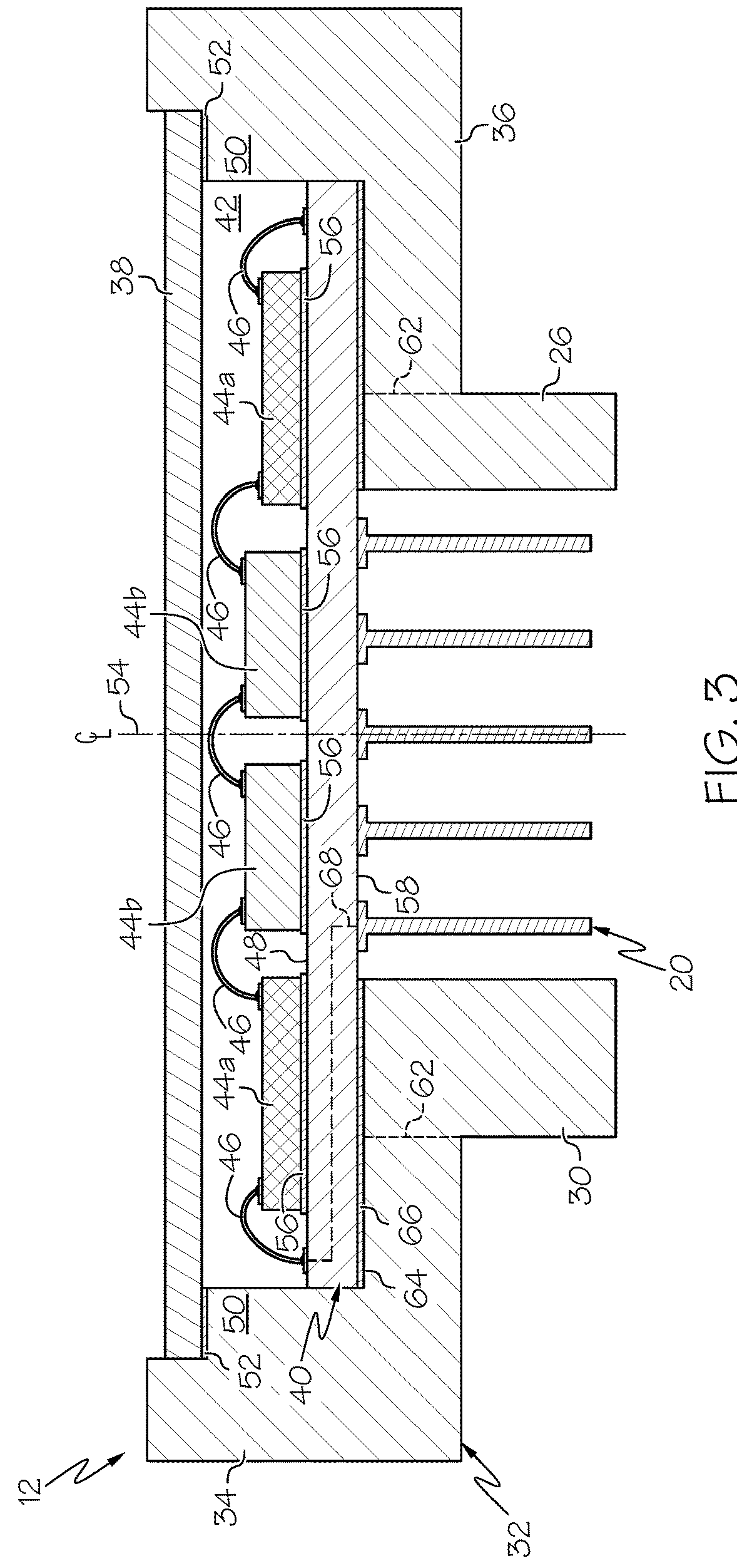
[0035]The following describes avionic LRUs having increased temperature tolerances and other desirable properties, as well as aircraft systems containing such high temperature avionic LRUs. Embodiments of the below-described avionic LRUs are usefully produced for compatibility with existing LRU receptacles of the type present onboard ci...


PUM


Abstract

Avionic LRUs having increased temperature tolerances and other desirable properties are provided, as are aircraft systems containing such high temperature avionic LRUs. In one embodiment, the avionic LRU includes at least one microelectronic device and an LRU housing, which contains an enclosed cavity in which the microelectronic device is located. The LRU housing further includes an electrically-routed housing wall having an inner principal surface or frontside, which partially bounds the enclosed cavity and to which the microelectronic device is bonded or attached. The avionic LRU further includes a first LRU connector interface having a first LRU terminal array. The first LRU terminal array projects from the LRU housing and is electrically coupled to the microelectronic device through the electrically-routed housing wall. The LRU connector interface is configured to matingly engage the receptacle connector interface to support LRU operation when the LRU is removably mounted to the avionic LRU receptacle.

Description

TECHNICAL FIELD[0001]The present invention relates generally to aircraft and, more particularly, to avionic LRUs having increased temperature tolerances and other desirable properties, as well as to aircraft systems containing such high temperature avionic LRUs.ABBREVIATIONS[0002]The following abbreviations appear throughout this document:[0003]AM—Additive Manufacturing or Additively Manufactured;[0004]ASIC—Application Specific Integrated Circuit;[0005]CAD—Computer Aided Design;[0006]COTS—Commercial Off The Shelf;[0007]FFF—Fused Filament Fabrication;[0008]GTE—Gas Turbine Engine;[0009]LRU—Line Replaceable Unit;[0010]MCM—Multichip Module;[0011]MEMS—Microelectromechanical Systems;[0012]MES—Main Engine Start;[0013]PWB—Printed Wiring Board;[0014]RF—Radio Frequency;[0015]SLA—Stereolithography;[0016]SMD—Surface Mount Device;[0017]wt %—weight percentage;[0018]vol %—volume percentage; and[0019]3D—three dimensional.BACKGROUND[0020]Modern aircraft are commonly equipped with relatively large nu...

Claims


Application Information

Patent Timeline
IPC IPC(8): H02B1/26H02B1/28H01R13/631H01R13/52B64D43/00
CPCH02B1/26H02B1/28H01R13/631H01R13/5219B64D43/00B64D47/00H01R13/64Y02T50/50
Inventor SLOAT, JEFFREY
Owner HONEYWELL INT INC
Why Eureka
Try Eureka