
Crack-free fabrication of near net shape powder-based metallic parts

a technology of powder-based metallic parts and crack-free fabrication, which is applied in the field of powder-based metallurgy, can solve the problems of compacts that are relatively fragile, have minimal fracture toughness, and may be encountered, and achieve the effect of reducing or eliminating the possibility of cracking of powder compacts, substantially eliminating the residual tensile stress of powder compacts, and reducing or eliminating the possibility of biaxial tensile stress

Active Publication Date: 2018-08-14
SUBARU CORP +1
View PDF14 Cites 0 Cited by
  • Summary
  • Abstract
  • Description
  • Claims
  • Application Information

AI Technical Summary

Benefits of technology

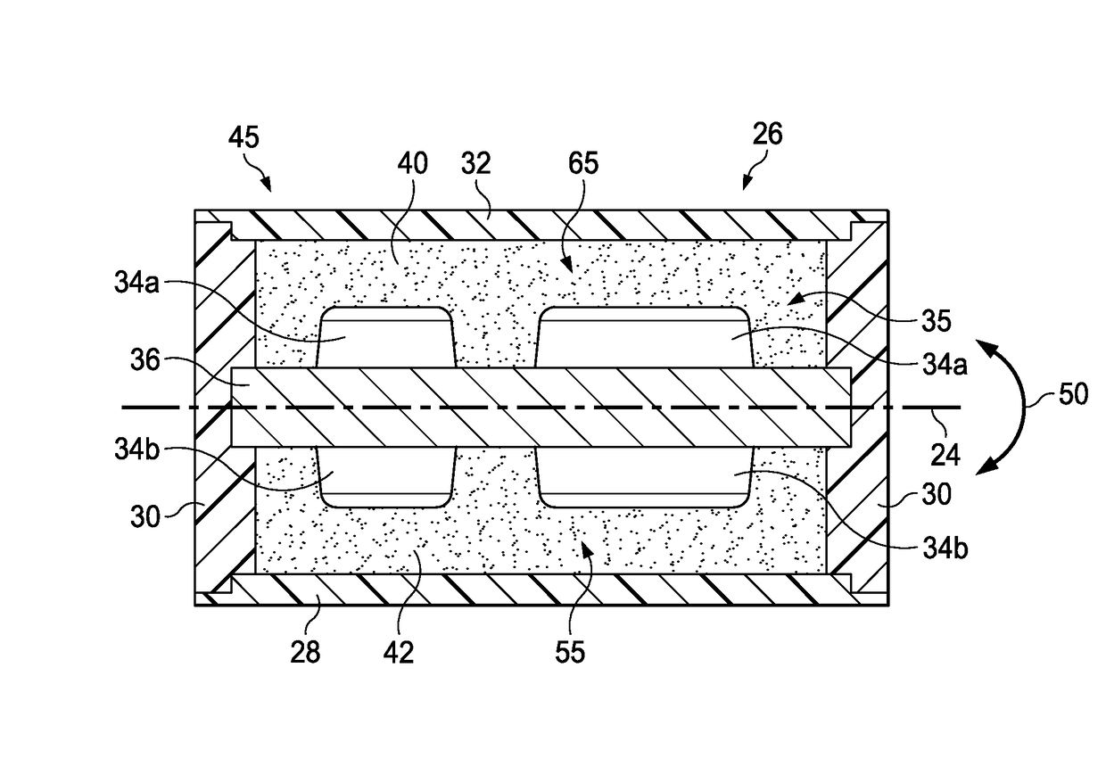
The disclosed embodiments enable the fabrication of non-cracked metallic powder parts using a process called direct consolidation. This process involves using a flexible container and a die component to shape the powder and react the compaction forces. By placing the die component in a way that prevents bending, and introducing metallic powder in layers around the die component, the method reduces biaxial tensile stresses and the possibility of cracking. The resulting powder compacts are also more uniform and reliable. Another embodiment of the method involves making the die component relatively stiff and introducing layers of soft material to balance the loading during compaction. The soft material can be introduced as a layer of metallic powder or as a separate layer. Overall, the method allows for the fabrication of high-quality metallic powder parts without the need for expensive or complex processes.

Problems solved by technology

Problems may be encountered where the die includes internal die components for forming features or details of the part.
For example, where the internal die components are asymmetrically shaped or arranged, the applied compaction pressure may impose unbalanced loads on the die components which cause them to bend or deform.
At this stage of processing, the compact is relatively fragile and has minimal fracture toughness because the powder particles in the compact are not yet metallurgically bonded together.
Consequently, in some cases, the tensile forces generated by flex-back of the internal die components may cause undesired deformation of the compact, and / or localized cracking of the compact.

Method used


Image

  • Crack-free fabrication of near net shape powder-based metallic parts
  • Crack-free fabrication of near net shape powder-based metallic parts
  • Crack-free fabrication of near net shape powder-based metallic parts

Examples


Embodiment Construction

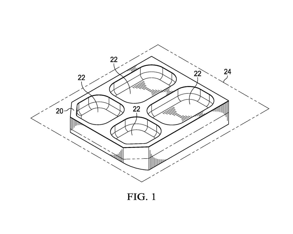
[0025]The disclosed embodiments provide a method and die assembly for fabricating crack-free, direct consolidated, near net shape (NNS) powder-based metallic parts. For example, referring to FIG. 1, the disclosed embodiments may be employed to fabricate a generally rectangular metallic part 20 which may have one or more details or features such as recesses 22. The part 20 is fabricated by compacting a desired metallic powder into a green powder compact substantially matching the shape of the part 20, and then sintering the powder compact into a solid part. The disclosed embodiments may be employed to fabricate parts from a wide range of metallic powders and alloys, including, without limitation titanium alloy powders such as hydride-dehydride blended-elemental powder for the titanium alloy SP 700, or Ti-6Al-4V.

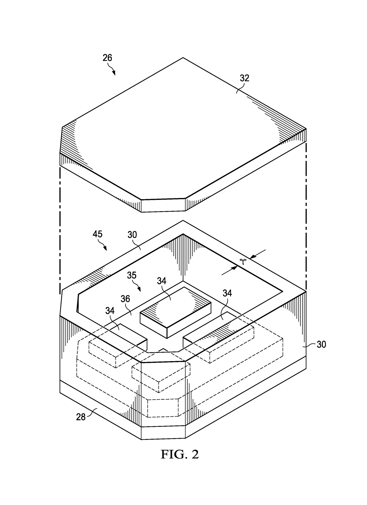
[0026]Referring now to FIGS. 2 and 3, the part 20 shown in FIG. 1 may be fabricated using a direct consolidation technique in which metallic powder is formed into a powder com...


PUM

PropertyMeasurementUnit
metallicaaaaaaaaaa
stiffnessaaaaaaaaaa
flexibleaaaaaaaaaa

Abstract

Crack-free powder-based, near net shaped parts are fabricated using a die assembly and cold isostatic pressing. Soft materials are introduced on both sides of die components in order to balance compression loads applied to the die component, and thereby avoid deformation of the die component.

Description

BACKGROUND INFORMATION[0001]1. Field[0002]The present disclosure generally relates to the powder metallurgy, and deals more particularly with a method and die for fabricating crack-free direct consolidated powder-based metallic parts.[0003]2. Background[0004]Powder metal technology is sometimes used to produce near-net-shape (NNS) metallic parts, eliminating the need for metal removal processes such as machining, and thereby reducing costs. Blended, fine powder materials such as titanium alloys are compacted into the shape of a part, known as a compact. The compact is then sintered in a controlled atmosphere to bond the powder materials into a finished part. In one compaction process known as cold isostatic compaction (CIP), a flexible die is filled with metallic powder and placed in a press where it is immersed within a working medium, such as a liquid. The press compresses the liquid, causing a compaction pressure to be uniformly applied around the surface of the die. The die flex...

Claims


Application Information

Patent Timeline
Patent Type & Authority Patents(United States)
IPC IPC(8): B22F3/04B30B11/00B22F1/00B22F3/00B22F3/12B22F3/02B22F3/16C22C14/00
CPCB22F3/04B22F1/0003B22F3/003B22F3/02B22F3/1216B22F3/16B30B11/00C22C14/00B22F2998/10B22F2301/205B22F3/10B22F1/00B30B11/001B22F3/15B30B15/02
Inventor EL-SOUDANI, SAMI M.SANDERS, DANIEL GORDONYAJIMA, SHINICHI
Owner SUBARU CORP
Learn More