Drive clutch

a clutch and clutch technology, applied in the direction of gearing, gearing elements, hoisting equipment, etc., can solve the problems of belt failure, relative low vehicle speed, and early and more frequent replacement, so as to reduce wear on components, increase efficiency, and reduce wear.

Active Publication Date: 2018-08-21
ZULAWSKI DENNIS
View PDF85 Cites 3 Cited by
  • Summary
  • Abstract
  • Description
  • Claims
  • Application Information

AI Technical Summary

Benefits of technology

[0009]An aspect of the present disclosure relates to a drive clutch having a torque transfer mechanism between the engine and the moveable sheave configured to reduce wear on components of the drive clutch by eliminating the sliding contact between a moveable sheave and a drive shaft member. The torque transfer mechanism for increasing efficiency and reducing wear may comprise a torque bellows, which is configured to more efficiently transfer torque from the engine to the moveable sheave upon radial compression of the torque bellows, by being attached to the stationary shaft and the moveable sheave through a cover. Sliding blocks and corresponding slide tracks are concentrically positioned between the moveable sheave and the shift plate and centrifugal force provides a force for linear movement for the sliding blocks, which results in axial movement of the moveable sheave, which can act to compress the torque bellows and to move the moveable sheave axially as well as radially. This configuration reduces costs because precise machining is not needed and reduces premature wear and tear on the drive clutch.

Problems solved by technology

When the primary clutch radius is smaller than the secondary clutch radius, the secondary shaft turns at a rate that is slower than the engine speed, resulting in a relatively low vehicle speed.
The cam arm and roller type clutches are prone to premature wear of the cam arm and the roller, which results in earlier and more frequent replacement.
The calibration of force on the belt can also produce excessive belt heat, which results in belt failure.
As both types of clutches used today have varying functional limitations, calibrating a clutch for desired performance often results in undesired inherited clutch characteristics.
Drive clutch systems of the prior art lack durability due to wear and tear caused by radial movement from the engine.
Engines develop instantaneous RPM changes during operation and produce torsional vibration and varying inputs.
Prior art methods of minimizing this wear including improving machining tolerance, precision improvements to assembly practices and using higher quality material, all of which increase the costs associated with the clutch device.

Method used


Image

  • Drive clutch
  • Drive clutch
  • Drive clutch

Examples


Embodiment Construction

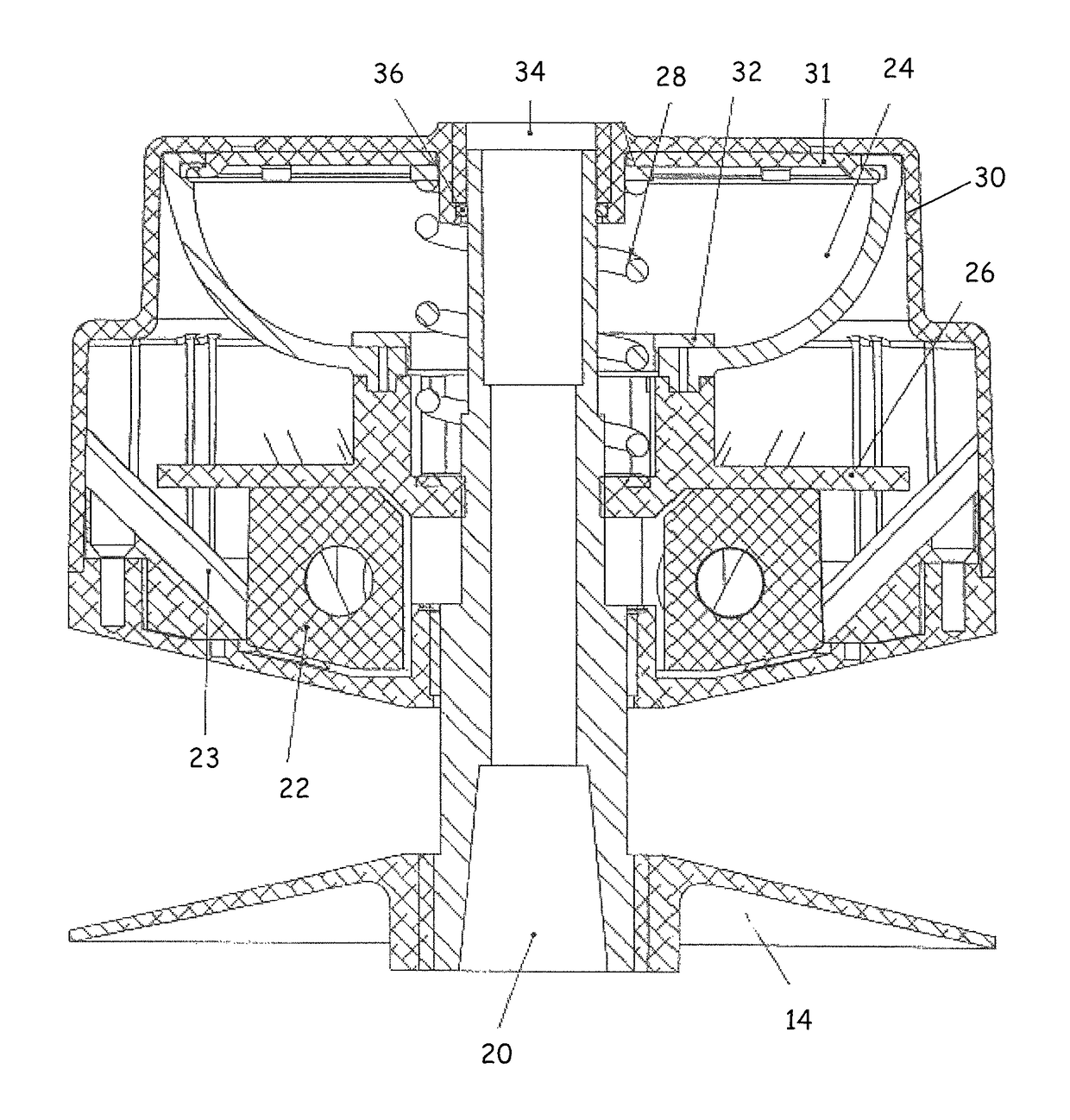
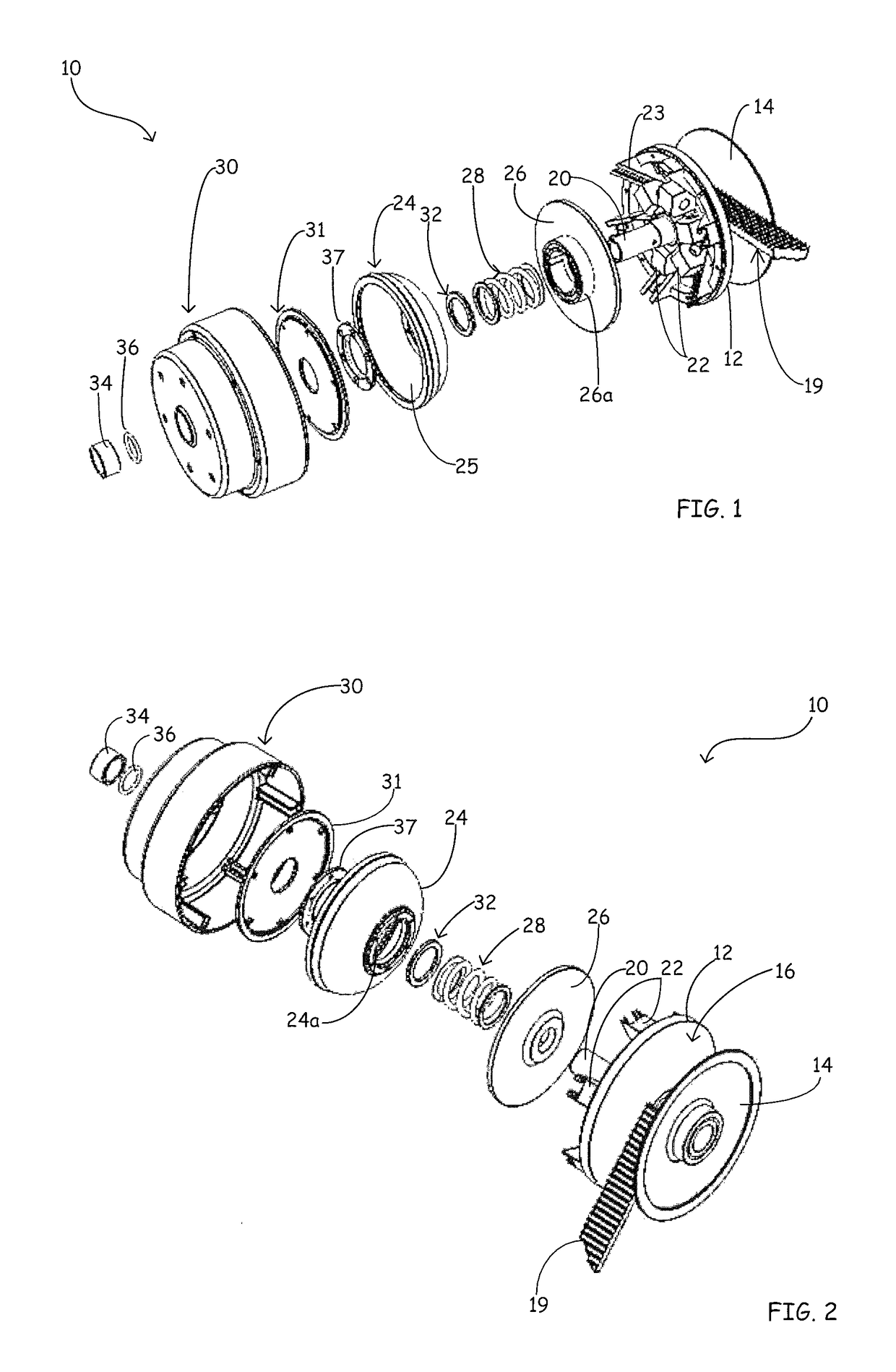
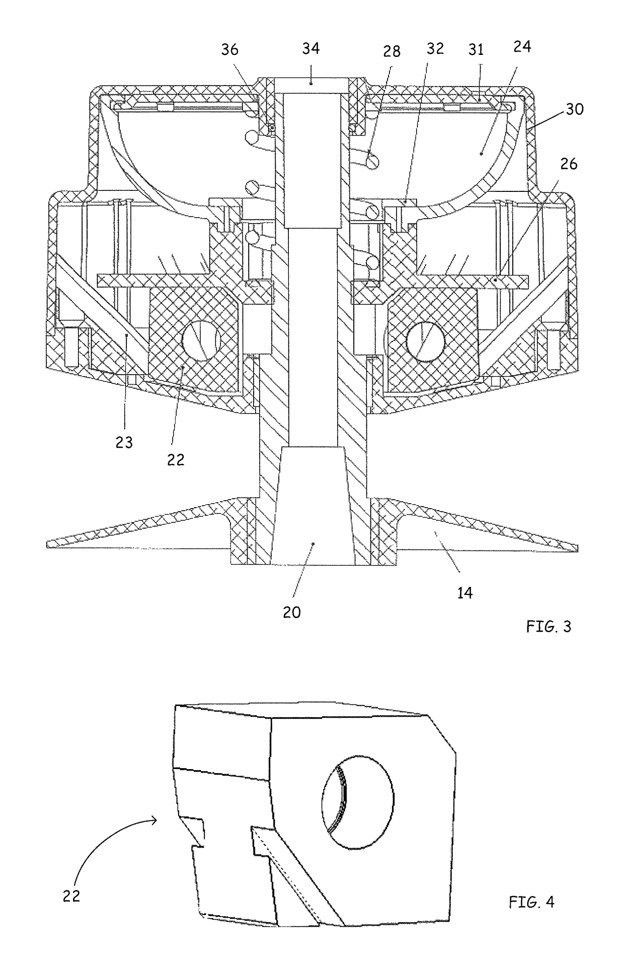
[0020]The present disclosure is directed to a clutch assembly for belt-type continuously variable transmissions (CVT) which are used in relatively small motorized vehicles, such as snowmobiles, all-terrain vehicles (ATV's), tractors, motor scooters, go-carts and golf carts. The clutch assembly of the present disclosure is configured to more effectively transfer torque from an engine to a moveable sheave of the clutch assembly. In one embodiment of the present disclosure, the clutch assembly incorporates a torque bellows. The torque bellows is compressible and compression of the torque bellows results from the transfer of torque from the engine to the moveable sheave. This disclosure is further directed to a method of controlling the forces generated by shift blocks by incorporating a control mechanism. The control mechanism may comprise a control device such as a modulator. It is further contemplated that an interface of the control device can be operable with various smart systems ...


PUM


Abstract

A drive clutch having a compressible torque transfer mechanism configured to transfer torque from an engine or motor to a moveable sheave and configured to reduce wear on components of the drive clutch by eliminating sliding contact between surfaces to transfer torque and change the gear ratio. The torque transfer mechanism increases efficiency and reduces wear and may comprise a torque bellows, which is configured to transfer torque from the engine to the moveable sheave upon radial compression of the torque bellows. Sliding blocks and corresponding slide tracks are concentrically positioned between the moveable sheave and the shift plate and centrifugal force provides a force for linear movement for the sliding blocks, which results in movement of the moveable sheave and the cover, which can act to compress the torque bellows. This configuration reduces costs because precise machining is not needed and reduces premature wear and tear on the drive clutch.

Description

BACKGROUND OF THE INVENTION[0001]Various relatively small motorized vehicles, such as snowmobiles, all-terrain vehicles (ATV's), tractors, motor scooters, go-carts and golf carts use an endless belt type continuously variable transmission (CVT). Variable transmissions include a variable-input drive / driving / primary pulley or clutch and an output driven / secondary pulley or clutch. The drive pulley is connected to the crankshaft of the engine. The driving pulley is also called the input pulley because it is where the energy from the engine enters the transmission. The second pulley is called the driven pulley because the first pulley turns it. As an output pulley, the driven pulley transfers energy to the driveshaft of the track drive. Each pulley is composed of a fixed sheave or pulley half that is fixed in the axial direction, and a movable sheave or pulley half, which is movable in the axial direction. A high strength metal or rubber belt, such as a V-belt, joins the drive pulley an...

Claims


Application Information

Patent Timeline
Patent Type & Authority Patents(United States)
IPC IPC(8): F16H59/00F16H63/00F16H61/00F16H55/56F16H9/12
CPCF16H9/12F16H55/56
Inventor ZULAWSKI, DENNIS
Owner ZULAWSKI DENNIS
Why Eureka
Try Eureka