
Passive heat and mass transfer system

a mass transfer system and passive technology, applied in the direction of vacuum distillation separation, separation process, lighting and heating apparatus, etc., can solve the problems of system limitations and negatively affect heat transfer efficiency, and achieve the effect of enhancing the efficiency of the heat and mass transfer system and efficient evaporation ra

Active Publication Date: 2018-08-28
COFLO TECH LLC
View PDF12 Cites 0 Cited by
  • Summary
  • Abstract
  • Description
  • Claims
  • Application Information

AI Technical Summary

Benefits of technology

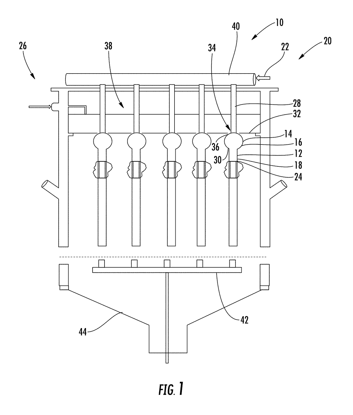
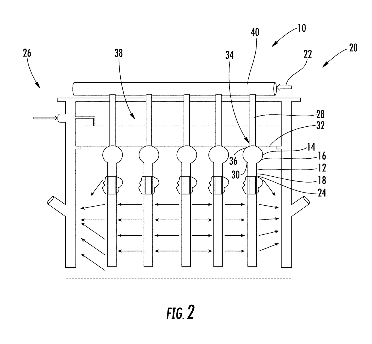
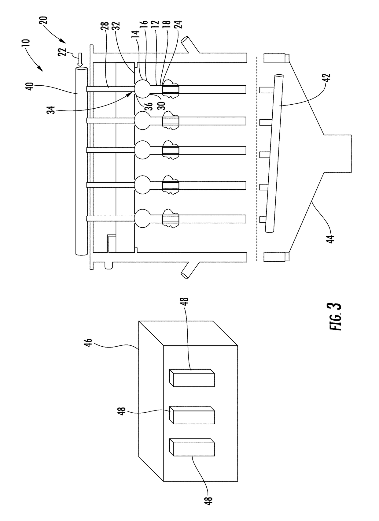
The heat and mass transfer system described in this patent is a passive system that uses gravitational force to create a thin liquid film flow on an outer surface of a flow distribution head and downstream conduit member. This system is more efficient than conventional systems because it allows for faster evaporation rates and better heat transfer. The flow distribution head can be formed from any shape that creates a uniform distribution of a liquid film, and the heat transfer medium, such as steam, passes through the downstream conduit to enhance efficiency. The system also minimizes the temperature gradient between the feed liquid and the wall of the downstream conduit, reducing the formation of scale. Overall, this heat and mass transfer system is more efficient and effective than conventional systems.

Problems solved by technology

These systems experience a number of limitations.
In addition, conventional systems experience scale formation and buildup on the interior surfaces of the tubes, which also negatively affects heat transfer efficiency.

Method used


Image

  • Passive heat and mass transfer system
  • Passive heat and mass transfer system
  • Passive heat and mass transfer system

Examples


Embodiment Construction

[0050]As shown in FIGS. 1-35, a heat and mass transfer system 10 configured to be a passive system using gravitational force to form a flow of thin liquid film 12 on an outer surface 14, 24 of an flow distribution head 16 and downstream conduit member 18 to subject the thin liquid film 12 to heat transfer mediums 22 is disclosed. The flow distribution head 16 may be formed from any shape capable of creating a liquid distribution on an outer surface 14, 24 of the flow distribution head 16. This configuration creates more efficient evaporation rates. In particular, in embodiments where the heat transfer medium passing within the downstream conduit 18 is steam, the steam is passed within the downstream conduit. The steam condenses and forms condensate droplets, which can form a film, on the inner surfaces of the downstream conduit 18, but the incoming steam forces the condensate droplets out of the downstream conduit 18, thereby preventing the condensate droplets from remaining on the ...


PUM

PropertyMeasurementUnit
thicknessaaaaaaaaaa
thicknessaaaaaaaaaa
temperatureaaaaaaaaaa

Abstract

A heat and mass transfer system configured to be a passive system using gravitational force to form a thin liquid film flow on an outer surface of a flow distribution head and downstream conduit member to subject the thin liquid film to heat transfer mediums. The at least partially spherical flow distribution head creates a uniform thin flow of liquid on the outer surface increasing the efficiency of the heat and mass transfer system. The heat and mass transfer system may include a heat transfer medium supply system in fluid communication with internal aspects of the downstream conduit such that a heat transfer medium flows within the downstream conduit while the liquid film flows on the outer surface of the downstream conduit. Rather than conventional sheet flow on inner surfaces of a conduit, the flow distribution head enables sheet flow to be formed on an outside surface of a component.

Description

CROSS-REFERENCE TO RELATED APPLICATION[0001]This application claims the benefit of U.S. Provisional Patent Application No. 62 / 171,505, filed Jun. 5, 2015, the entirety of which is incorporated herein.FIELD OF THE INVENTION[0002]This invention is directed generally to heat and mass transfer systems, and more particularly to thin sheet flow heat transfer systems configured to be passive systems using gravitational flow resulting from a unique flow distribution configuration.BACKGROUND[0003]Conventional evaporators are typically formed from a plurality of tubes contained within a shell. Feed liquid is passed within the evaporator tubes, and hot gases or liquids are passed on the outside of the evaporator tubes to heat the tubes. Conventional evaporator tubes are configured such that a feed liquid to be heated forms a liquid film on inner surfaces of a conduit. The outer surfaces of the conduit is typically surrounded with steam.[0004]There exist numerous types of evaporators. For examp...

Claims


Application Information

Patent Timeline
Patent Type & Authority Patents(United States)
IPC IPC(8): F28D3/02F28G13/00F28D21/00F28C1/14F28C1/02B01F3/04B01D1/22F28F25/06B01D1/00F28D3/04
CPCF28D3/02B01D1/0064B01D1/22B01F3/04F28C1/02F28D3/04F28D21/0015F28F25/06F28G13/00F28C1/14F28D2021/0064F25B39/04F28F25/02F28C1/00B01D1/065B01D1/26B01D3/10B01D5/0012C02F1/08B01D3/145B01D61/362Y02B30/70B01F23/20
Inventor JACHUCK, ROSHAN
Owner COFLO TECH LLC
Learn More