Long-travel track carriage and rising-rate suspension mechanism for a track-driven land vehicle

a technology of rising rate and track suspension, which is applied in the direction of convertible cycles, vehicle components, vehicles, etc., can solve the problems of affecting the stability of the vehicle, the track “footprint” is too small for adequate floatation, and the overall general discontinuous falling rate suspension, etc., to achieve maximum power transfer efficiency, increase the compression rate, and the effect of minimal track tension

a technology of rising rate and track suspension, which is applied in the direction of convertible cycles, vehicle components, vehicles, etc., can solve the problems of affecting the stability of the vehicle, the track “footprint” is too small for adequate floatation, and the overall general discontinuous falling rate suspension, etc., to achieve maximum power transfer efficiency, increase the compression rate, and the effect of minimal track tension

US10077088B1Active Publication Date: 2018-09-18WESTERN POWER SPORTS

Image

  • Long-travel track carriage and rising-rate suspension mechanism for a track-driven land vehicle
  • Long-travel track carriage and rising-rate suspension mechanism for a track-driven land vehicle
  • Long-travel track carriage and rising-rate suspension mechanism for a track-driven land vehicle

Examples


first embodiment

[0037]An variation to a snowbike conversion kit previously herein presented is illustrated in FIG. 7. The track skid 12B of this configuration is slightly different from the previous track skid 12 in that track rails 13B comprise upward-extending members with attitude-leveling strut pivot mounts 30 near the upper extremities of the upward-extending members of track rails 13B. A track skid attitude-leveling strut 29 connects pivotally between a pivot connection to a bell crank arm 24C and a cross-rod 31 mounted between attitude-leveling strut pivot mounts 30 of track rails 13B. Track attitude-leveling strut 29 is variable in length having a minimum compressed length and a maximum extended length. One embodiment of track attitude-leveling strut 29 is illustrated with a view of its internal components in FIG. 8, and comprises a piston 33, a coil spring 34 that resists the compression of strut 29 from a centered position and a second coil spring 35 that resists the extension of strut 29...

second embodiment

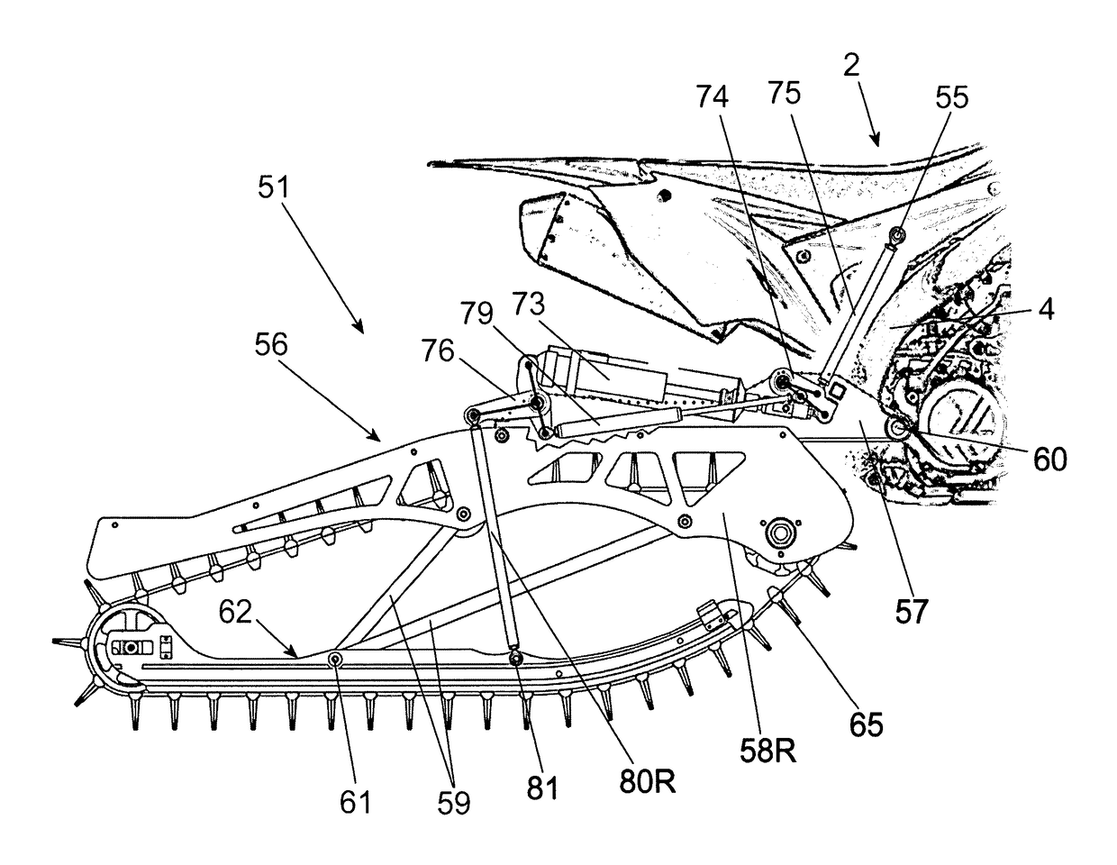
[0041]Referring now to the side view illustration of FIG. 11, the alternate structure of this second embodiment will be described. A snowbike track carriage and suspension mechanism 51 is illustrated and described mounted to a chassis 4 of a motorcycle 2 in place of the motorcycle's rear wheel and swingarm. A rigid swingarm frame assembly 56 comprises a swingarm upper frame 57 illustrated in FIG. 11 with the left side member cutaway and its outline indicated using a dotted line to provide better visibility of components being described. Rigid swingarm frame 56 additionally comprises a left side plate 58L (not visible in this view) and a right side plate 58R all solidly affixed together. The rigid swingarm frame assembly 56 has a swingarm chassis pivot 60 that pivotally mounts to the motorcycle chassis 4 and a track skid pivot 61 that pivotally mounts to a track skid 62. Track skid 62 comprises a left track rail 63L (not visible in this view), a right track rail 63R, rear idler wheel...


PUM


Abstract

A long-travel continuously-rising-rate track carriage and suspension mechanism for motive drive and cushioned support of a tracked land vehicle upon a ground-contacting lower run of an endless-loop track. A present practical application of the invention is to convert a motorcycle into a snowbike for over-snow use wherein the rear wheel and swingarm of the motorcycle are replaced by the track carriage and suspension mechanism of the present invention and the front wheel is replaced by one or more skis. The unique long-travel rising-rate track suspension is accomplished employing a single swingarm connected pivotally between the vehicle chassis and a track skid, and using a bell crank and connecting rod to provide progressive actuation of a shock absorber upon compression of the track suspension. The track is carried and driven by components mounted to the single swingarm.

Description

BACKGROUND OF THE INVENTION[0001]Snowbikes have become increasingly popular and ubiquitous for over-snow recreation over the past 10 years. Several manufacturers have designed, produced and marketed snowbike conversion systems (“kits”) to allow the seasonal conversion of motorcycles into snowbikes that ride and handle like motorcycles when ridden on snow. These motorcycle-like riding and handling characteristics have engendered a new powersport recreation genre with rapidly-growing popularity.[0002]The majority of present snowbike kit designs employ track suspension designs previously used in snowmobiles. These snowbike kit designs typically utilize a suspension “tunnel” like a snowmobile that is an accessory frame that is rigidly mounted to the motorcycle chassis swingarm and shock absorber mounts to extend rearward from the motorcycle chassis. This frame mounts to the motorcycle chassis to form a rigid frame under which the track skid and suspension are deployed. Most of these sno...

Claims


Application Information

Patent Timeline
18 Sep 2018
Publication
US10077088B1
IPC
B62M27/02; B62D55/104
CPC
B62D55/104; B62M27/02; B62M2027/026; B62D55/07; B62K13/00; B62M29/00; B62M2027/021; B62M2027/022
Inventors
FORBES, VERNAL DELLOY