Vehicle interior LED lighting system

a technology for led lighting and interiors, applied in television systems, lighting and heating apparatuses, instruments, etc., can solve the problems of slow retooling of existing incandescent lighted mirror assembles, mirror manufacturers that have their current production of mirror assemblies tooled for incandescent light source applications, and cannot take full advantage of the recent developments in the use of non-incandescent light sources. achieve the effect of efficient power generation and maximum power transfer efficiency

Inactive Publication Date: 2007-03-27
DONNELLY CORP
View PDF195 Cites 945 Cited by
  • Summary
  • Abstract
  • Description
  • Claims
  • Application Information

AI Technical Summary

Benefits of technology

[0035]The present invention includes use of a direct current (DC) step-down voltage conversion element in order to allow a single high-intensity power LED (or at most two or three individual LEDs connected electrically in series or a plurality of individual LEDs connected electrically in parallel) be efficiently powered with maximum power transfer efficiency between the powering DC source (typically the vehicle battery or ignition system) and the LED being powered, and with minimum need to dissipate power as heat in a resistive element (such as a series power resistor capable of dissipating power of the level of about 1 watt and higher, and sometimes in conjunction with a heat sink / heat dissipater) and / or to use the like of pulse width modulation or similar circuitry to vary the duty cycle being applied to the individual LED being powered.

Problems solved by technology

Some manufacturers are slower to retool existing incandescent lighted mirror assembles to accommodate LEDs and, as a result, have and will continue to have a large inventory of mirror assemblies that are tooled for incandescent light sources.
When mirror assemblies are tooled for incandescent light sources, these mirror assemblies have heretofore been limited to using incandescent-light-source replacements for the incandescent light sources.
Therefore, mirror manufacturers that have their current production of mirror assemblies tooled for incandescent light source applications have not been able to take full advantage of the recent developments in the use of non-incandescent light sources.

Method used


Image

  • Vehicle interior LED lighting system
  • Vehicle interior LED lighting system
  • Vehicle interior LED lighting system

Examples


Embodiment Construction

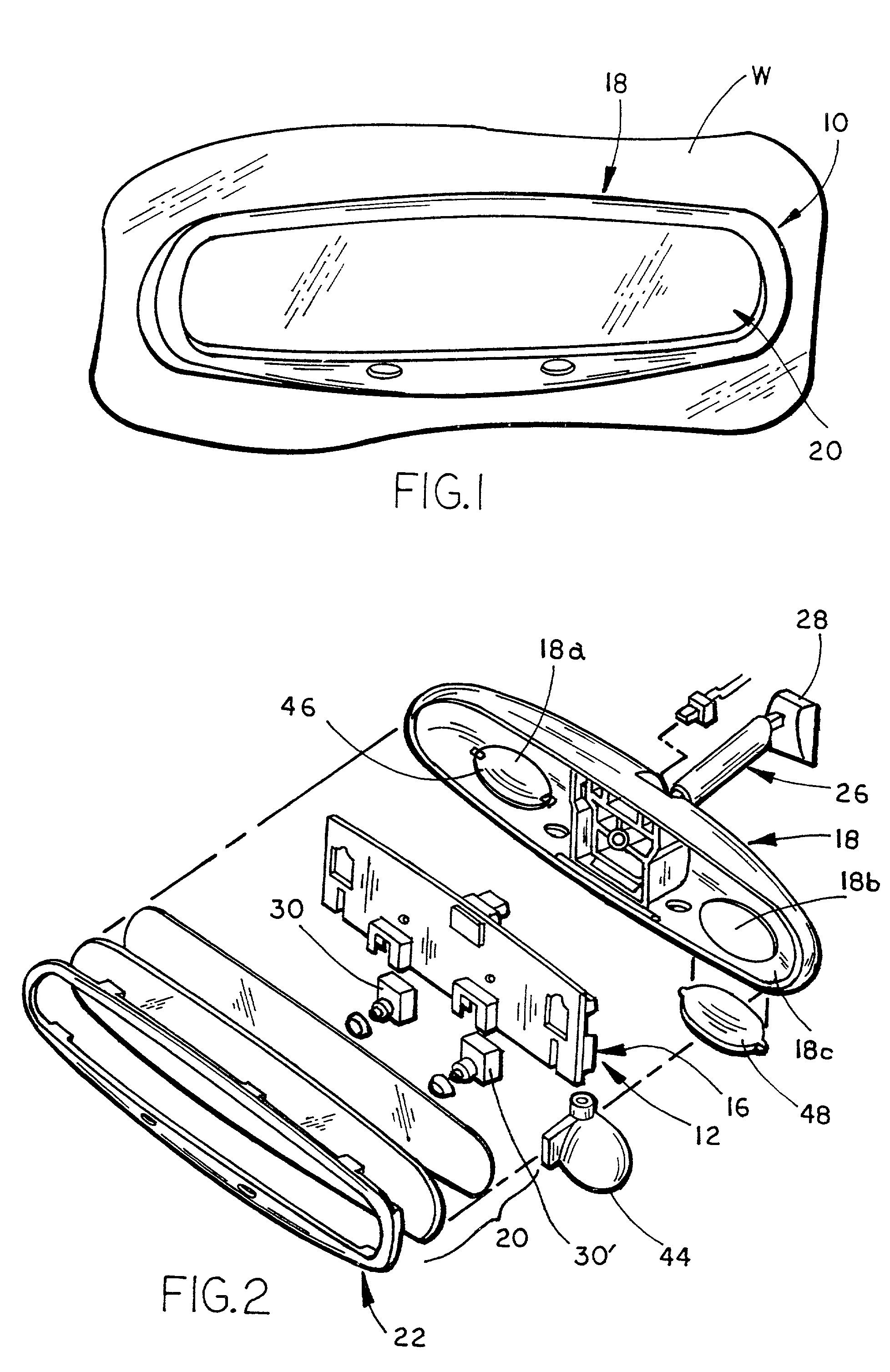
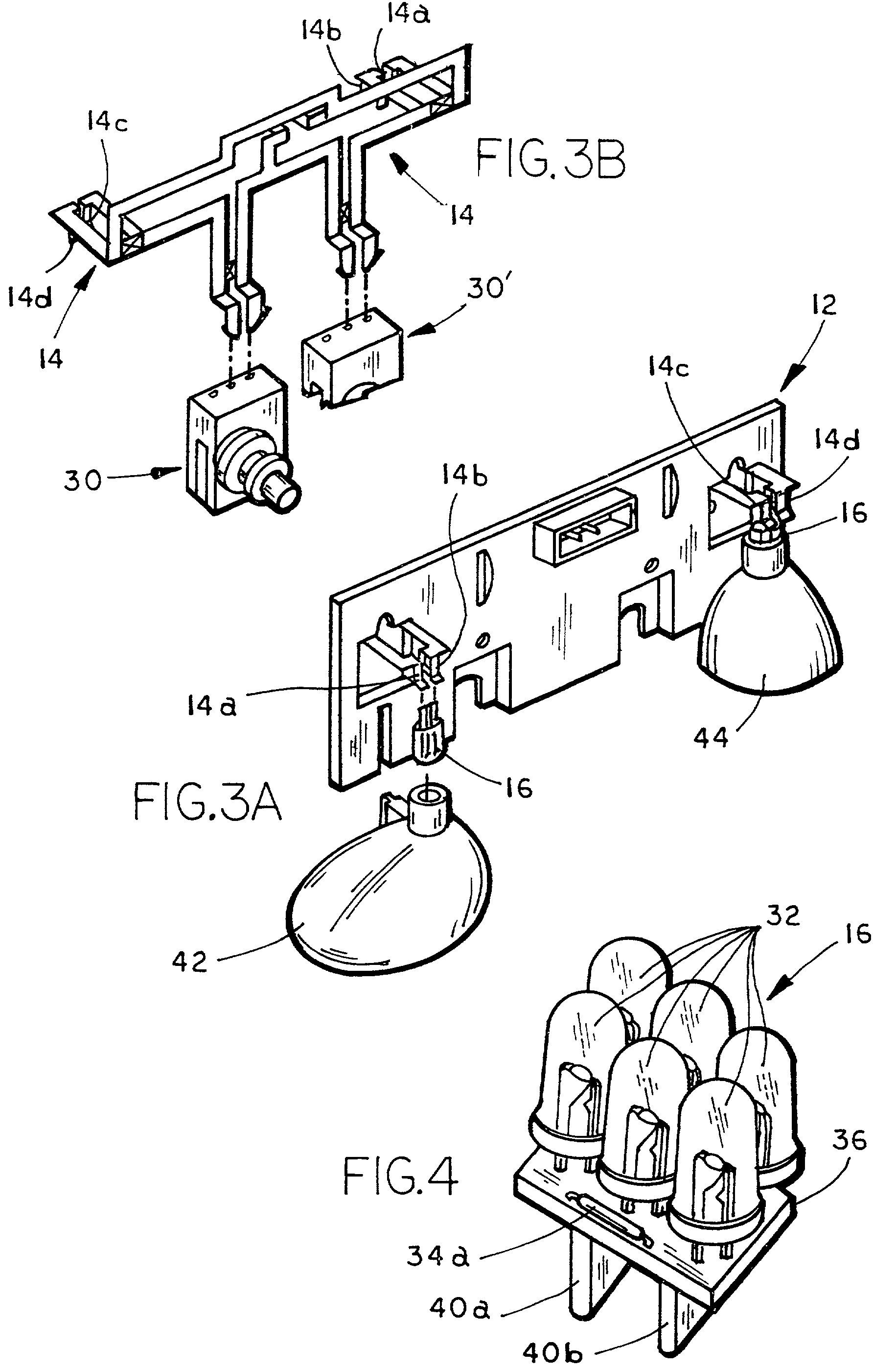
[0083]Referring to FIG. 1, the numeral 10 generally designates an interior rearview mirror assembly which incorporates at least one non-incandescent light source unit / module 16 of the present invention. As will be more fully described below, rearview mirror assembly 10 includes a carrier 12 with an incandescent light source circuit member 14 (FIG. 4) to which non-incandescent light source unit / module 16 is electrically coupled in an incandescent light source socket (formed by contact elements 14a, 14b or 14c, 14d). Thus, non-incandescent light source unit 16 provides a replacement for a conventional incandescent light source, such as a filament light bulb. Alternatively, light source unit 16 may be electrically coupled via connections or contacts to corresponding connectors or contacts of other circuits that are connected to the vehicle ignition battery. In this manner, light source unit 16 provides a compact and serviceable light source that can be used in a wide variety of applica...


PUM


Abstract

A vehicle lighting system for a vehicle includes an accessory module assembly that is adapted for attachment to an interior portion of a vehicle and configured to illuminate, for example, an area inside the vehicle. The module assembly includes a single high-intensity power light emitting diode that has a luminous efficiency of at least about 1 lumen per watt when the light emitting diode is operated and is preferably operated at a forward current of at least 100 milliamps. The system also includes a voltage conversion element for converting the battery/ignition voltage of the vehicle to the forward operating voltage of the light emitting diode.

Description

[0001]This application claims priority from and incorporates by reference herein in their entireties U.S. Provisional Application Ser. No. 60 / 346,733, filed Jan. 7, 2002, entitled IMPROVED VEHICULAR LIGHTING SYSTEM, by Applicants John O. Lindahl and Niall R. Lynam, U.S. Provisional Applications Ser. No. 60 / 263,680, filed Jan. 23, 2001; Ser. No. 60 / 271,466, filed Feb. 26, 2001; and Ser. No. 60 / 315,384, filed Aug. 28, 2001, and is a continuation-in-part of U.S. Utility patent application Ser. No. 09 / 793,002, entitled VIDEO MIRROR SYSTEMS INCORPORATING AN ACCESSORY MODULE, filed Feb. 26, 2001, now U.S. Pat. No. 6,690,268.TECHNICAL FIELD AND BACKGROUND OF THE INVENTION[0002]The present invention relates to automotive lighting, more specifically to lighted mirrors for a vehicle, such as an automobile, sports utility vehicle, truck or similar road transportation vehicle. More particularly, the present invention relates to a lighting system that incorporates at least one non-incandescent l...

Claims


Application Information

Patent Timeline
Patent Type & Authority Patents(United States)
IPC IPC(8): B60Q1/26F21V29/00B60Q1/32B60Q3/02B60R1/12B60R11/00B60R11/02B60R11/04F21V29/505G02B6/00G02B27/00
CPCB60K35/00H04N7/183B60Q1/2665B60Q1/323B60Q3/004B60Q3/023B60R1/12B60R1/1207B60R11/0235B60R11/04B60D1/36B60D1/58B60R1/00B60K37/06B60K2350/1024B60K2350/1028B60R2011/0026B60R2011/0033B60R2011/0082B60R2011/0084B60R2011/0089B60R2011/0282B60R2011/0288B60R2011/0294G02B6/00G02B2027/0118G02B2027/012Y10S362/80B60R2300/808B60Q3/64B60Q3/258B60K2370/143B60K2370/1438B60Q1/247H04N23/661H04N23/63G06V20/52G06V20/593H04N23/11H04N23/56H04N23/74H04N25/76B60R1/003B60R2300/10B60R2300/20B60R2300/308G09G3/3406G09G3/3648G09G2320/0626G09G2380/10B60Q3/82B60Q3/74B60R1/04B60R2001/1253B60R2300/8006
Inventor LYNAM, NIALL RLINDAHL, JOHN O
Owner DONNELLY CORP
Why Eureka
Try Eureka