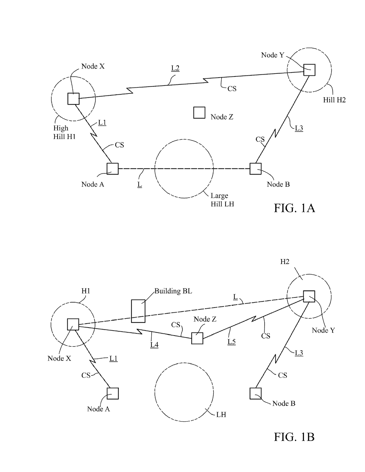
Generally speaking, the only limitation on the placement of the nodes is that intermediate nodes in a
route of three or more nodes should be within
sight of at least two other nodes.
However, it is not obvious how general concepts behind radio mesh systems comprising fixed-location, ground-based receiving and transmitting nodes can be adapted to a
system in which the nodes are satellites orbiting the earth.
While this approach works technically, it is believed to have proved impracticable from a commercial standpoint because it was too costly to implement, although as noted above, it still has utility in certain specialized applications.
In addition, the satellites still require expensive onboard
attitude control hardware such as positioning thrusters and
rocket fuel for them, both of which add extra weight and thus increase the cost of delivering the satellites into
orbit.
In addition, the '354 patent does not disclose how to provide satellite-to-satellite communications between randomly orbiting satellites.
Such satellites might be more expensive and heavier, thus increasing launch costs, but other factors might offset the increased cost because fewer satellites might need to be launched.
However, one issue that must be addressed when communicating data transmissions over the radio
route is that a single antenna in a node cannot both transmit and receive signals simultaneously.
One drawback is the necessity of providing sufficient separation between the respective frequency bands to ensure that the there is no interference when an antenna is transmitting and receiving at the same time.
On the one hand, greater beam width will increase the probability that a beam match can be created, but a greater beam width reduces the
gain of the antenna.
Conversely, a narrower beam will increase
antenna gain, but reduce the probability of creating a beam match between nodes.
This trade-off is particularly significant in the satellite nodes because the satellite antenna configuration has to take into consideration constraints on the weight and size of the satellites, which limits the number of antennas the satellite can carry, and on the electrical power available from onboard batteries.
Thus, while there may be delays in completing a particular
data transmission while a new radio route is created in mid-transmission, that potential drawback will be offset by the fact that the higher
gain radio beams made feasible by using rotating satellites will be more likely to establish radio routes by which data transmissions between certain ground stations can be made in the first place.
In addition, to the assumptions underlying the above description, there may not be at any given time two counter-rotating satellites over an area where α radio route is desired between two ground stations.
If the satellites are rotating at the same
angular velocity, this situation can persist for an extended period of time, thus weakening a radio link between the satellites, or perhaps preventing the establishment of a link altogether.
The data communications might be delayed while the radio route is intermittently disrupted and refreshed as different antennas on the two satellites disalign and realign.
Any resulting delays while beam matches are created may be tolerable if the alternative is an inability of a particular ground station to send and receive data transmissions at all.
For example, even though the earth's
atmosphere is extremely thin at low-earth orbital altitudes, the region in which satellites used in the present system will preferably occupy, orbiting objects nevertheless still experience
aerodynamic drag.
The situation is made more complex because the creation of beam matches between system nodes depends on numerous other factors, such as those discussed previously, so that optimizing system performance entails more than just a trade-off among competing antenna configurations.
While it will be well within the ability of one skilled in the art to design and implement an operable system in accordance with the above-described embodiments, such systems may prove to have certain performance issues, such as requiring inordinate amounts of time to assemble multiple acceptable radio links into a radio route between ground stations, which in turn may
delay call transmissions.
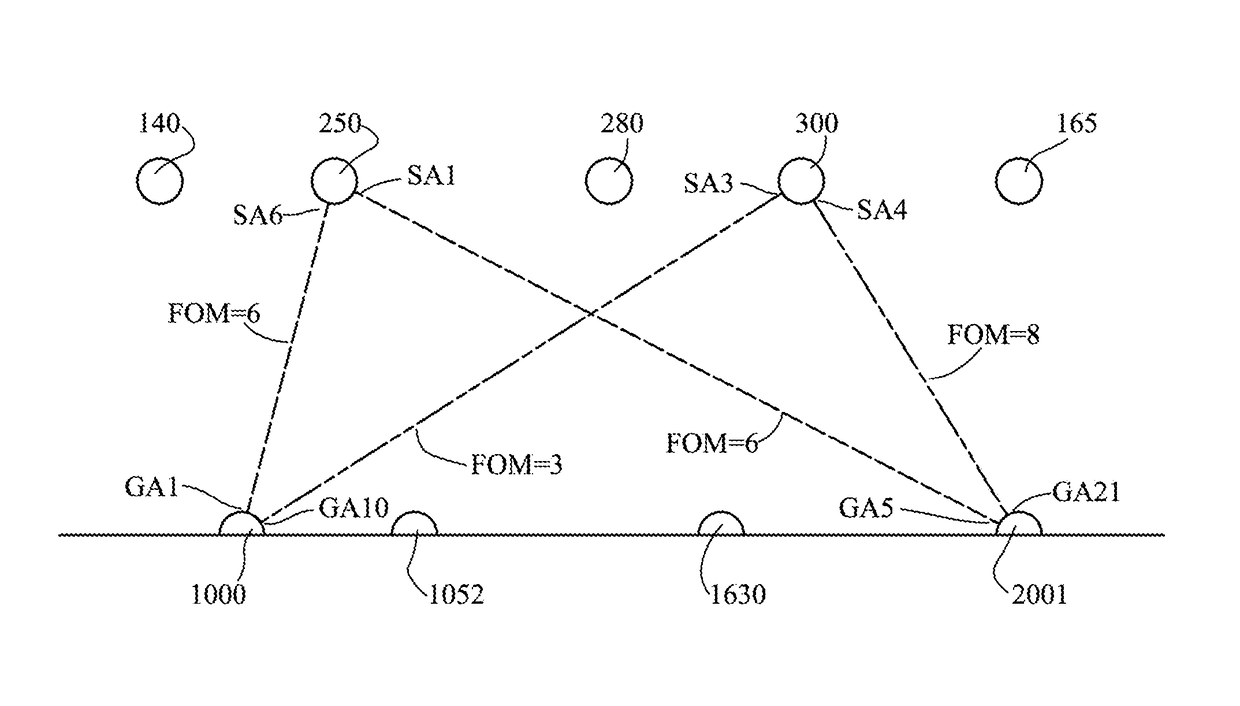
This further increases the probability of rapidly creating a radio route between two ground stations.
Thus, although addition of the figures of merit in a single satellite route will typically result in an optimum or preferred route, more complex and sophisticated algorithms may be necessary to implement this aspect of the invention when choosing between potential single- and multiple-satellite routes or between two potential multiple-satellite routes.

