Method of manufacturing porous current collector

a technology of porous current collector and manufacturing method, which is applied in the manufacture of hybrid capacitor electrodes, cell components, hybrid/edl, etc., can solve the problems of deterioration of the productivity of the porous current collector, and achieve the effect of reducing the manufacturing cost and improving productivity

Active Publication Date: 2018-10-09
KOREA JCC CO LTD
View PDF4 Cites 5 Cited by
  • Summary
  • Abstract
  • Description
  • Claims
  • Application Information

AI Technical Summary

Benefits of technology

[0008]Another object of the present invention is to provide a method of manufacturing a porous current collector, which can reduce a manufacturing cost of a porous current collector and improve productivity because a porous current collector is fabricated in such a way as to fabricate alcohol-resolvable resin as an etch mask pattern by printing polyhydric alcohol in a pattern and to form a plurality of through holes in a metal sheet using the etch mask pattern.

Problems solved by technology

The photolithography process has a complicated manufacturing process because it requires an exposure process using a mask pattern, and thus has a problem in that the productivity of the porous current collector may be deteriorated.

Method used


Image

  • Method of manufacturing porous current collector
  • Method of manufacturing porous current collector
  • Method of manufacturing porous current collector

Examples


first embodiment

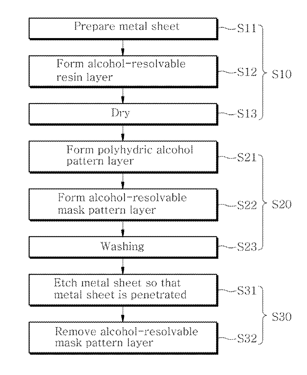
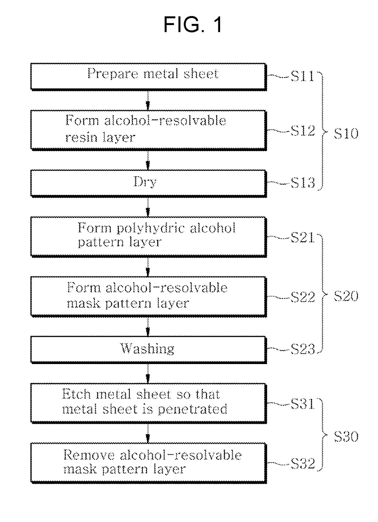
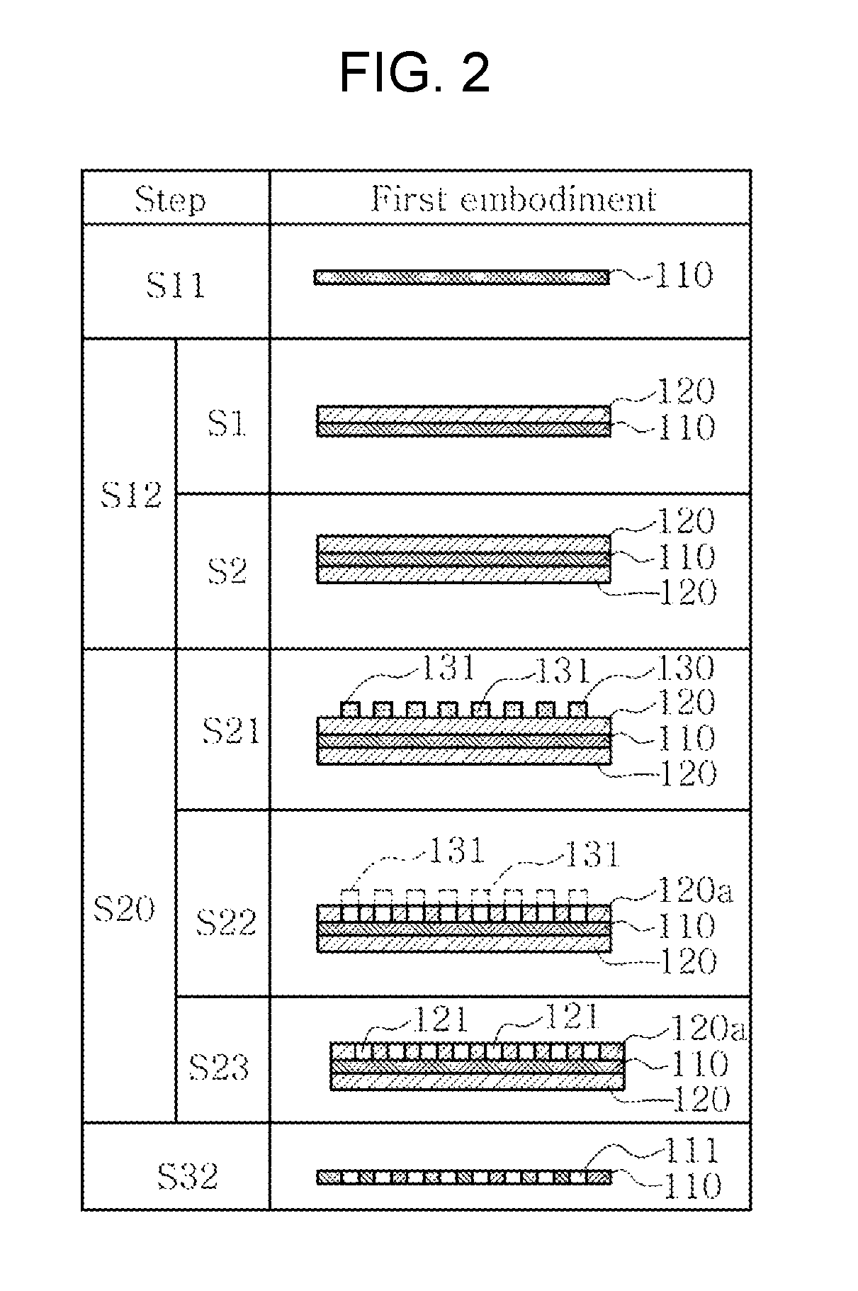
[0021]In step S10 of forming the alcohol-resolvable resin layer 120, first, as shown in FIGS. 1 and 2, the metal sheet 110 is prepared (S11). That is, the metal sheet 110 shown in step S11 of FIG. 2 is prepared. The metal sheet 110 shown in step S11 of FIG. 2 is a cross-sectional view taken along line A-A of the metal sheet 110 shown in FIG. 3. One of aluminum (Al), copper (Cu), nickel (Ni) and chrome (Cr) or a mixture of two or more materials of aluminum (Al), copper (Cu), nickel (Ni) and chrome (Cr) is used as the material of the metal sheet 110. In this case, FIG. 2 shows a method of manufacturing a porous current collector according to an embodiment of the present invention.

[0022]After the metal sheet 110 is prepared, as shown in FIGS. 1 and 2, the alcohol-resolvable resin layer 120 is formed by coating the alcohol-resolvable resin on a surface of the metal sheet 110 (S12). After the metal sheet 110 is prepared as in step S12 of FIG. 2, the alcohol-resolvable resin layer 120 is ...

second embodiment

[0030]Another embodiment, that is, the method of manufacturing a porous current collector according to an embodiment of the present invention, is shown in FIG. 6.

[0031]In the method of manufacturing a porous current collector according to the second embodiment shown in FIG. 6, step S10 of forming the alcohol-resolvable resin layer 120 by coating alcohol-resolvable resin on a surface of the metal sheet 110 and step S30 of etching the metal sheet 110 using the alcohol-resolvable mask pattern layer 120a as a mask so that the plurality of through holes 111 is formed in the metal sheet 110 after the alcohol-resolvable mask pattern layer 120a is formed are the same as those of the method of manufacturing a porous current collector according to the first embodiment, and thus a description thereof is omitted.

[0032]In the method of manufacturing a porous current collector according to an embodiment of the present invention, after the alcohol-resolvable resin layer 120 according to the second...


PUM

PropertyMeasurementUnit
temperatureaaaaaaaaaa
wt %aaaaaaaaaa

Abstract

Provided is a method of manufacturing a porous current collector, which can fabricate a porous current collector in such a way as to fabricate alcohol-resolvable resin as an etch mask pattern by printing polyhydric alcohol on a surface of the alcohol-resolvable resin in a pattern and to form a plurality of through holes in a metal sheet using the etch mask pattern. The method includes the steps of forming an alcohol-resolvable resin layer by coating alcohol-resolvable resin on a surface of a metal sheet, forming an alcohol-resolvable mask pattern layer by printing polyhydric alcohol on a surface of the alcohol-resolvable resin layer after the alcohol-resolvable resin layer is formed, and etching the metal sheet so that a plurality of through holes is formed in the metal sheet using the alcohol-resolvable mask pattern layer as a mask after the alcohol-resolvable pattern layer is formed.

Description

BACKGROUND OF THE INVENTION1. Technical Field[0001]The present invention relates to a method of manufacturing a porous current collector and, more particularly, to a method of manufacturing a porous current collector, which can fabricate a porous current collector in such a way as to fabricate alcohol-resolvable resin as an etch mask pattern by printing polyhydric alcohol on a surface of the alcohol-resolvable resin in a pattern and to form a plurality of through holes in a metal sheet using the etch mask pattern.2. Description of the Related Art[0002]A super capacitor or secondary cell, such as an electric double layer capacitor (EDLC), includes a current collector. A porous current collector is used as the current collector in order to prevent a reduction of the capacity or output due to a reduction of binding strength with an electrode material attributable to a change with the passage of time. A plurality of through holes is formed in the porous current collector in order to pre...

Claims


Application Information

Patent Timeline
Patent Type & Authority Patents(United States)
IPC IPC(8): H01G11/84C23F1/02C23F1/16H01G11/70
CPCH01G11/84C23F1/02C23F1/16H01G11/70H01G11/28C23F1/18C23F1/20H01M4/661H01M4/72Y02E60/10Y02E60/13
Inventor SHIN, JIN SIKSHIN, DAL WOOLEE, MUN SOOKIM, SUNG HANOH, MI HYUNYUN, HYUNPARK, JI YOONLEE, KYOUNG NAM
Owner KOREA JCC CO LTD
Why Eureka
Try Eureka