Current and voltage control circuit and method for a class II LED driver

Active Publication Date: 2018-10-09
UNIVERSAL LIGHTING TECHNOLOGIES
View PDF12 Cites 12 Cited by
  • Summary
  • Abstract
  • Description
  • Claims
  • Application Information

AI Technical Summary

Benefits of technology

[0015]It is desirable to consolidate voltage and current control loops to reduce the size and cost of the t

Problems solved by technology

However, class II isolation current and voltage control is not easy to implement using the flyback converter of FIG. 1.
Traditional current and voltage control methods such as those implemented via the system illustrated in FIG. 1 have at least two

Method used


Image

  • Current and voltage control circuit and method for a class II LED driver
  • Current and voltage control circuit and method for a class II LED driver
  • Current and voltage control circuit and method for a class II LED driver

Examples


Example

[0039]While the making and using of various embodiments of the present invention are discussed in detail below, it should be appreciated that the present invention provides many applicable inventive concepts that can be embodied in a wide variety of specific contexts. The specific embodiments discussed herein are merely illustrative of specific ways to make and use the invention and do not delimit the scope of the invention.

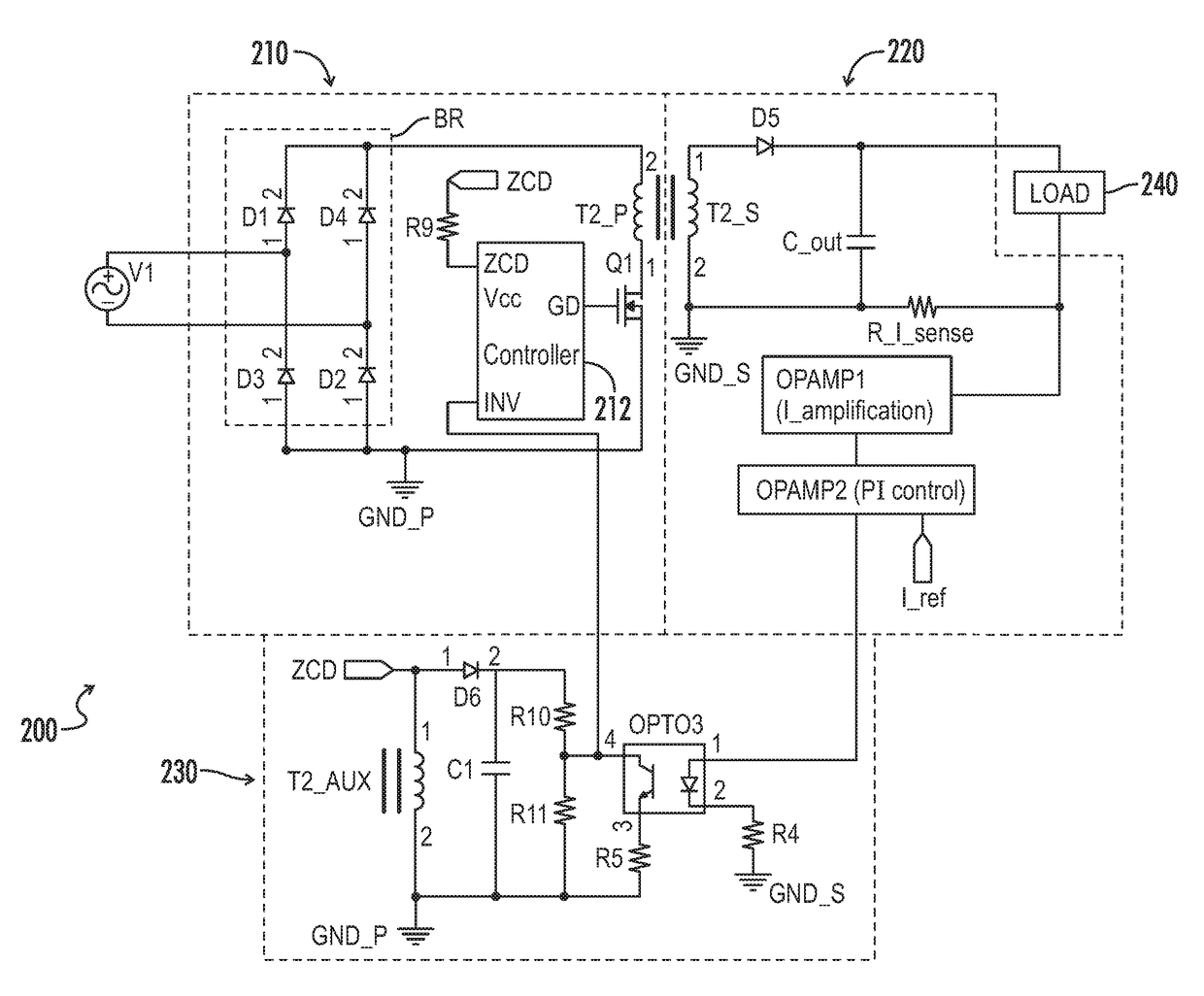
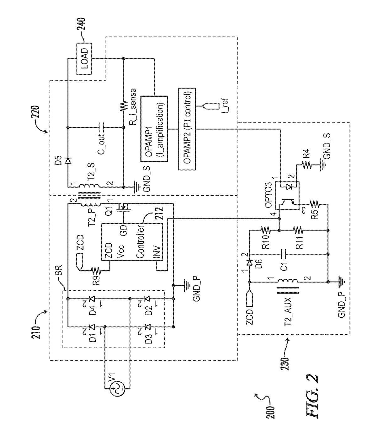
[0040]Referring generally to FIGS. 2-3, exemplary light emitting diode (LED) drivers, flyback converter configurations, lighting fixtures, and associated methods are now illustrated in greater detail. Where the various figures may describe embodiments sharing various common elements and features with other embodiments, similar elements and features are given the same reference numerals and redundant description thereof may be omitted below.

[0041]FIG. 2 illustrates an exemplary driver circuit 200 having consolidated voltage and current control loop for a flyback c...


PUM


Abstract

A driver circuit includes a combined current and voltage control circuit for driving a light emitting diode (LED) load. The driver circuit includes an isolation transformer having primary, secondary, and auxiliary windings. A primary side circuit is coupled to the primary winding and includes a power factor controller and a switch. The power factor controller controls an output current to the LED load by controlling an operational state of the switch. A secondary side circuit is coupled to the secondary winding. The secondary side circuit includes a proportional and integration (PI) control portion which outputs a control signal. A combined voltage and current control circuit is coupled to the auxiliary winding and includes an optocoupler coupled to the power factor controller and to the PI control section. The combined voltage and current control circuit transmits a control signal from the PI control section to the power factor controller.

Description

CROSS-REFERENCES TO RELATED APPLICATIONS[0001]This application claims priority to and benefit of U.S. Provisional Patent Application No. 62 / 383,821, dated Sep. 6, 2016, entitled “Current and Voltage Control Circuit and Method for a Class II LED Driver,” and which is hereby incorporated by reference in its entirety.[0002]A portion of the disclosure of this patent document contains material that is subject to copyright protection. The copyright owner has no objection to the reproduction of the patent document or the patent disclosure, as it appears in the U.S. Patent and Trademark Office patent file or records, but otherwise reserves all copyright rights whatsoever.STATEMENT REGARDING FEDERALLY SPONSORED RESEARCH OR DEVELOPMENT[0003]Not ApplicableREFERENCE TO SEQUENCE LISTING OR COMPUTER PROGRAM LISTING APPENDIX[0004]Not ApplicableBACKGROUND OF THE INVENTION[0005]The present invention relates generally to current and voltage control in flyback converters. More particularly, the presen...

Claims


Application Information

Patent Timeline
IPC IPC(8): H05B37/02H05B33/08H05B44/00
CPCH05B33/0821H05B33/0842H05B45/24Y02B20/30H05B45/355H05B45/40H05B45/385Y02B20/40
Inventor XIONG, WEI
Owner UNIVERSAL LIGHTING TECHNOLOGIES
Why Eureka
Try Eureka