
Multicore fiber

a multi-core fiber and core technology, applied in the field of multi-core fibers, can solve the problems of difficult to escape the light of a higher-order mode, the design degree of freedom is limited to change the refractive index or the diameter of the core, and the core pitch cannot be decreased, so as to improve the degree of design freedom and improve the crosstalk

Active Publication Date: 2018-10-16
THE FUJIKURA CABLE WORKS LTD +1
View PDF19 Cites 3 Cited by
  • Summary
  • Abstract
  • Description
  • Claims
  • Application Information

AI Technical Summary

Benefits of technology

The patent text describes a type of fiber that has multiple cores. However, there is a problem with this type of fiber because the light can get trapped in the spaces between the cores and it becomes more difficult to escape the light. This limits the design of the fiber. As a result, the patent text proposes a new type of fiber that can improve design flexibility and allow for better management of the light.

Problems solved by technology

When communication is performed using light of a desired mode in a desired wavelength band, a range of obtained values of the refractive indexes or the diameters of the cores is narrow and there is a limitation in a degree of freedom for design to change the refractive indexes or the diameters of the cores adjacent to each other.
In addition, in the trench type multicore fiber, there is a tendency that it is hard to escape light of a higher-order mode in light propagated through a specific core or core element and a cutoff wavelength increases, when the core element is disposed to surround the specific core or core element.
Therefore, to suppress propagation of light of a higher-order mode as compared with a mode of light propagated when the core element exists alone, a core pitch cannot be decreased greatly and there is a limitation in a degree of freedom for design.

Method used


Image

  • Multicore fiber
  • Multicore fiber
  • Multicore fiber

Examples


examples

[0087]Hereinafter, contents of the present invention will be described more specifically using examples and comparative examples. However, the present invention is not limited thereto.

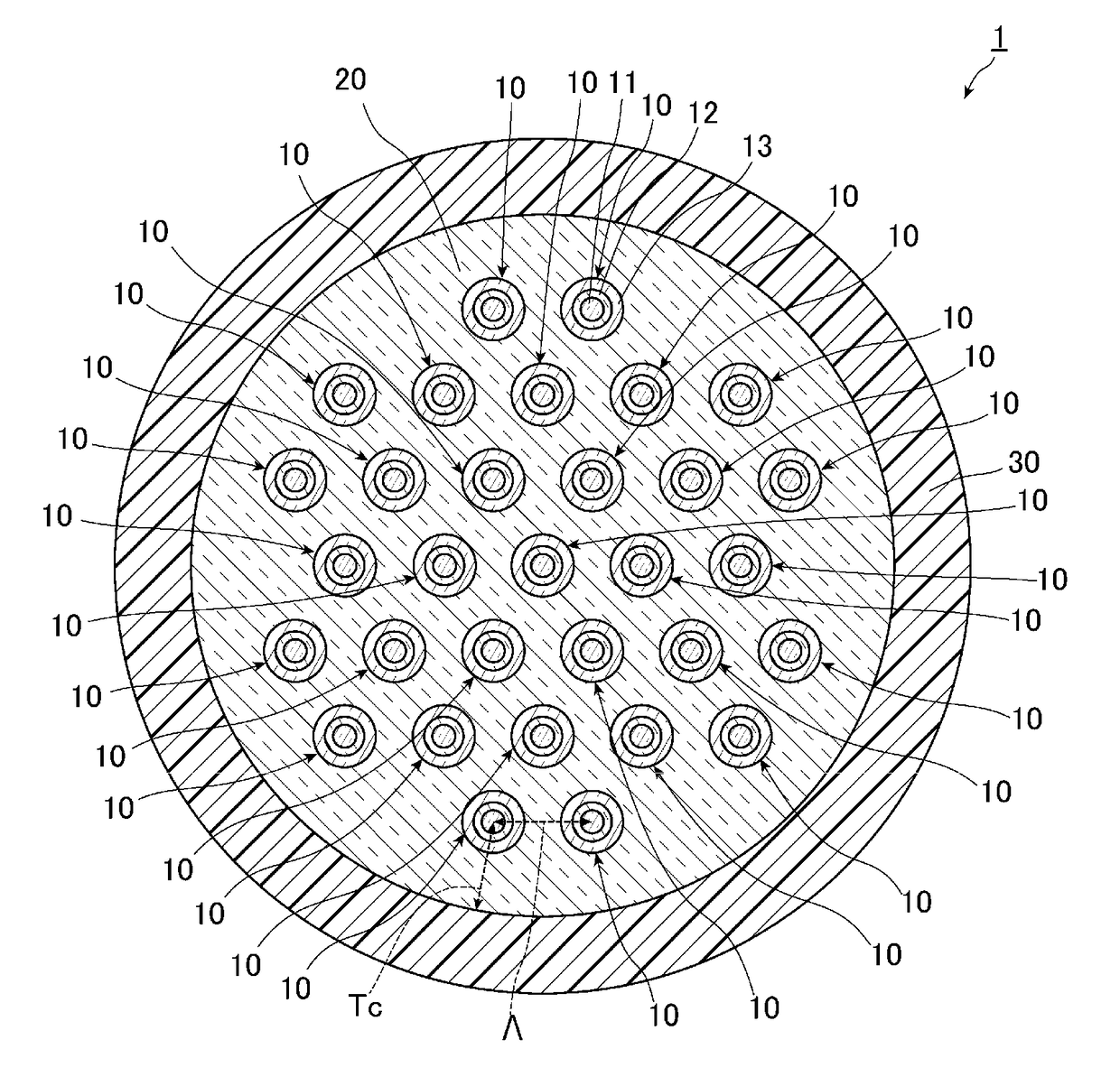
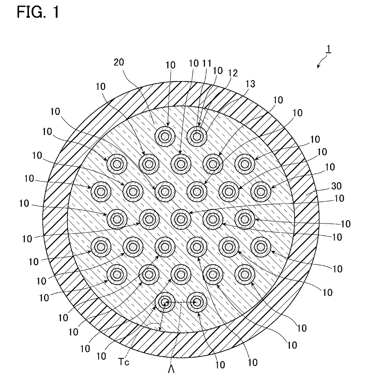
[0088]The multicore fiber 1 according to the first example of one or more embodiments was manufactured. An average value of the core pitch Λ of the manufactured multicore fiber 1 became 31.6 μm, an average value of the clad thickness Tc became 31.5 μm, an average value of the clad diameter became 231.0 μm, and an average value of an outer diameter of the cover layer 30 became 334.8 μm. In addition, a length was 11.2 km. The propagation loss of the light of the LP01 mode propagated through the multicore fiber 1 was measured. In addition, polarization mode dispersion PMD, a polarization loss difference PDL, an effective area Aeff, and a cable cutoff wavelength λc were measured. Results thereof are shown in Table 3. In Table 3, the cores 1 to 12 show the cores of the fourth layer in the first example of o...

second example

[0094]The multicore fiber 2 according to the second example of one or more embodiments was manufactured. An average value of the core pitch Λ of the manufactured multicore fiber 2 became 32.1 μm, an average value of the clad thickness Tc became 31.2 μm, an average value of the clad diameter became 230.8 μm, and an average value of an outer diameter of the cover layer 30 became 337.0 μm. In addition, a length was 10.5 km. Similarly to the first example, with respect to the multicore fiber 1, the crosstalk of the cores 11 adjacent to each other was measured. Results thereof are shown in Table 5. The cores described in a first column of Table 5 and the cores described in a second column thereof are cores adjacent to each other.

[0095]

TABLE 510.5 km (Measured XT)Excited coreMeasured coreXT11-11XT01-0189−9.2−4319−11.8−43.320−11.3−43.3175−12.3−45.56−9.4−4416−11.7−4227−10−42.32210−9.6−44.323−6−42.629−8.2−442614−9.3−43.615−8.5−44.325−8.9−42.631−7.7−40.83125−7.4−42.327−7.3−41.229−6.6−39.2

[009...

third example

[0097]The multicore fiber 4 according to the modification was manufactured. An average value of the core pitch Λ of the manufactured multicore fiber 4 became 32.4 μm, an average value of the clad thickness Tc became 29.9 μm, an average value of the clad diameter became 124.4 μm, and an average value of an outer diameter of the cover layer 30 became 220.0 μm. In addition, a length was 10.0 km. Similarly to the first example, with respect to the multicore fiber 4, propagation losses of the light of the LP01 mode and the light of the LP11 mode, polarization mode dispersion PMD, a polarization loss difference PDL, an effective area Aeff, and a cable cutoff wavelength λc were measured. Results thereof are shown in Table 6. In Table 6, the cores 1 to 6 show the cores disposed on the outer circumferential side and the core 7 shows the core disposed on the center of the clad.

[0098]

TABLE 6Propagationloss [dB / km]PMDPDLAeffLP01[ps / {square root over (km)}][dB][μm2]λcc155016251530-162515501625[μ...


PUM


Abstract

A multicore fiber communicates using light up to an xth-order LP mode (where x is an integer of 1 or more) in a communication band. The multicore fiber includes: a plurality of cores; a clad that surrounds the plurality of cores and has a refractive index lower than refractive indexes of the plurality of cores; and a cover layer that covers the clad and has a refractive index higher than the refractive index of the clad. Each of the plurality of cores propagates light up to an (x+1)th-order LP mode. A core pitch is set to a distance where crosstalk of the light up to the xth-order LP mode becomes less than or equal to −40 dB / km and crosstalk of light of the (x+1)th-order LP mode becomes greater than or equal to −30 dB / km.

Description

TECHNICAL FIELD[0001]The present invention relates to a multicore fiber and is suitable for improving a degree of freedom for design.BACKGROUND ART[0002]Presently, an optical fiber used for an optical fiber communication system spreading generally has a structure in which outer circumference of one core is surrounded by a clad and an optical signal is propagated through the core, so that information is transmitted. Recently, an amount of information transmitted increases drastically with the spread of the optical fiber communication system. According to the increase in the amount of information transmitted, in the optical fiber communication system, a large number of optical fibers such as dozens or hundreds of optical fibers are used and large-capacity long-distance optical communication is performed.[0003]It is known that, in the optical fiber communication system, a multicore fiber in which outer circumferences of a plurality of cores are surrounded by one clad is used and a plur...

Claims


Application Information

Patent Timeline
Patent Type & Authority Patents(United States)
IPC IPC(8): G02B6/02G02B6/44G02B6/036
CPCG02B6/02042G02B6/02G02B6/44G02B6/036G02B6/03694G02B6/02023G02B6/02014G02B6/0365
Inventor SASAKI, YUSUKETAKENAGA, KATSUHIROSAITOH, KUNIMASA
Owner THE FUJIKURA CABLE WORKS LTD
Learn More