Method for connecting a turbine blade or vane to a turbine disc or a turbine ring

a technology of turbine blades and turbine rings, which is applied in the direction of laser beam welding apparatus, electron beam welding apparatus, solventing media, etc., can solve the problems of high equipment investment, high welding speed, and inability to fusion welding turbine blades or vanes with great difficulty, etc., to achieve low equipment investment, low cost, and high welding speed

Active Publication Date: 2018-11-06
MTU AERO ENGINES GMBH
View PDF31 Cites 1 Cited by
  • Summary
  • Abstract
  • Description
  • Claims
  • Application Information

AI Technical Summary

Benefits of technology

[0030]In a further embodiment, it has proved to be advantageous if an electron beam welding process and/or a laser welding process and/or an inductive high-frequency pressure welding process and/or an i...

Problems solved by technology

However, this configuration has the effect that the turbine blades or vanes cannot be fusion welded or can only be fusion welded with great difficulty.
A connection to a turbine disk which can be fusion welded or a corresponding turbine ring, which can be manufactured from a nickel base alloy, is therefore not possible using conventional fusion welding processes and leads to considerable additional costs.
Alternatively, friction welding o...

Method used


Image

  • Method for connecting a turbine blade or vane to a turbine disc or a turbine ring
  • Method for connecting a turbine blade or vane to a turbine disc or a turbine ring
  • Method for connecting a turbine blade or vane to a turbine disc or a turbine ring

Examples


Embodiment Construction

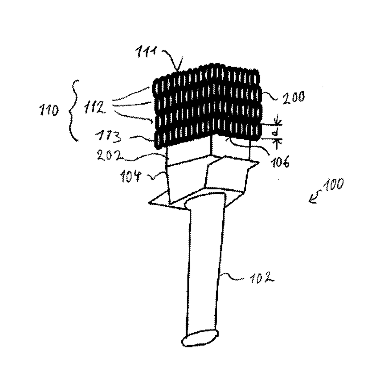
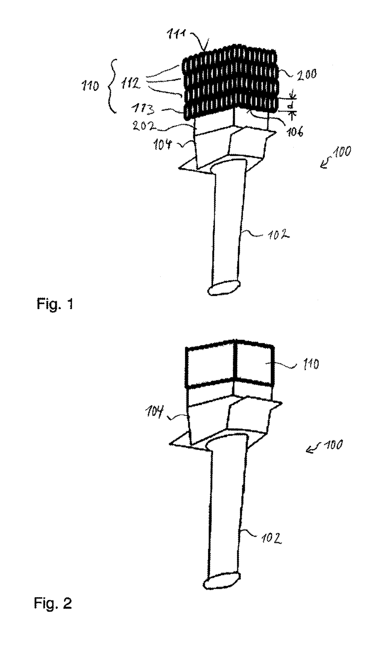
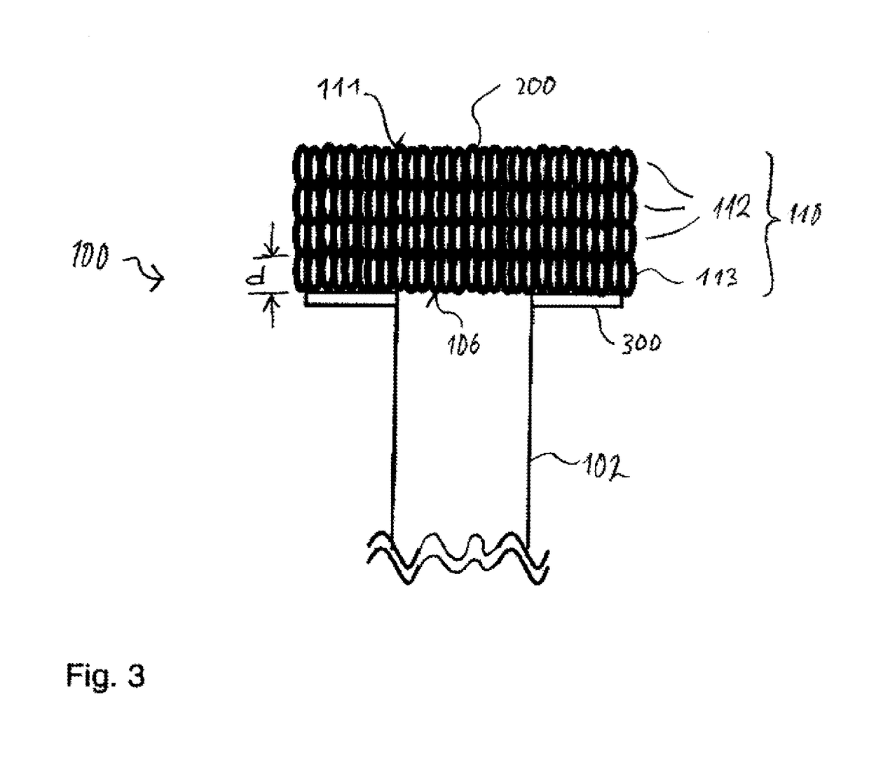
[0037]FIG. 1 shows a perspective view of a turbine blade or vane 100 for a turbomachine, such as e.g. a thermal gas turbine. The turbine blade or vane 100 has a main blade or vane part 102 and a blade or vane root 104, which both consist of a material 202 which is not suitable for fusion welding, such as a nickel-based cast material.

[0038]In order to connect the turbine blade or vane 100 to a turbine disk or a turbine ring (which are not shown), a connecting body 110 has been built up in a plurality of layers 113, 112 from an additive 200 suitable for fusion welding, such as e.g. the nickel-base material “INCONEL 718”, on a surface 106 located on a side of the blade or vane root 104 which faces away from the main blade or vane part 102. FIG. 1 shows a state in which the connecting body has been built up purely by way of example from four layers 200 lying one on top of another.

[0039]To form the connecting body 110 on the surface 106 of the turbine blade or vane 100, use is made for e...


PUM

PropertyMeasurementUnit
Thicknessaaaaaaaaaa
Thicknessaaaaaaaaaa
Thicknessaaaaaaaaaa

Abstract

The present invention provides a method for connecting a turbine blade or vane to a turbine disk or to a turbine ring. First, a connecting body is formed on the turbine blade or vane by supplying an additive suitable for fusion welding to a surface of the turbine blade or vane, melting the additive on the surface, with incipient melting of the surface, and allowing the additive and the surface to solidify. Then, the connecting body is connected to the turbine disk or to the turbine ring by means of a fusion welding process.

Description

BACKGROUND OF THE INVENTION[0001]1. Field of the Invention[0002]The invention relates to a method for connecting a turbine blade or vane to a turbine disk or a turbine ring for a turbine stage of a turbomachine, in particular of a thermal gas turbine. The invention furthermore relates to a turbine stage for a turbine of a turbomachine.[0003]2. Discussion of Background Information[0004]Such a method for connecting a turbine blade or vane to a turbine disk or a turbine ring and also such a turbine stage comprising a turbine disk or a turbine ring which is connected at least indirectly to one or more turbine blades or vanes are known from the prior art. The turbine stage serves for its part for arrangement in a single-stage or multi-stage turbine of a turbomachine formed, in particular, as a thermal gas turbine. Progression in the construction of gas turbines in this respect places ever higher demands on the materials used, however. The turbine blades or vanes serving as guide vanes or...

Claims


Application Information

Patent Timeline
IPC IPC(8): F01D5/30B23K26/342B23K15/00B23K26/32B23K35/02B23K35/24B23K101/00B23K103/18
CPCF01D5/3061B23K15/0006B23K15/0086B23K26/32B23K35/0244B23K35/24B23K26/342B23K2103/26B23K2101/001F05D2230/232F05D2230/237B23K2103/18
Inventor RICHTER, KARL-HERMANN
Owner MTU AERO ENGINES GMBH
Why Eureka
Try Eureka