Device and method for cooling a unit

a cooling device and cooling device technology, applied in the field of devices and cooling devices for cooling units, can solve the problems of inability to reduce the temperature of the object to be cooled, inability to cool down the object in time, and poor cooling process efficiency, so as to achieve short cooling down time and high efficiency

Inactive Publication Date: 2018-11-20
SIEMENS ENERGY GLOBAL GMBH & CO KG
View PDF33 Cites 0 Cited by
  • Summary
  • Abstract
  • Description
  • Claims
  • Application Information

AI Technical Summary

Benefits of technology

[0011]The object of the present invention is therefore to specify a method and a device for cooling a unit, which have

Problems solved by technology

As a result, this can result in impermissibly high mechanical stresses on the sensitive cold head.
Large temperature gradients in the cooled-down state in the unit to be cooled and at the cold head

Method used


Image

  • Device and method for cooling a unit
  • Device and method for cooling a unit
  • Device and method for cooling a unit

Examples


Embodiment Construction

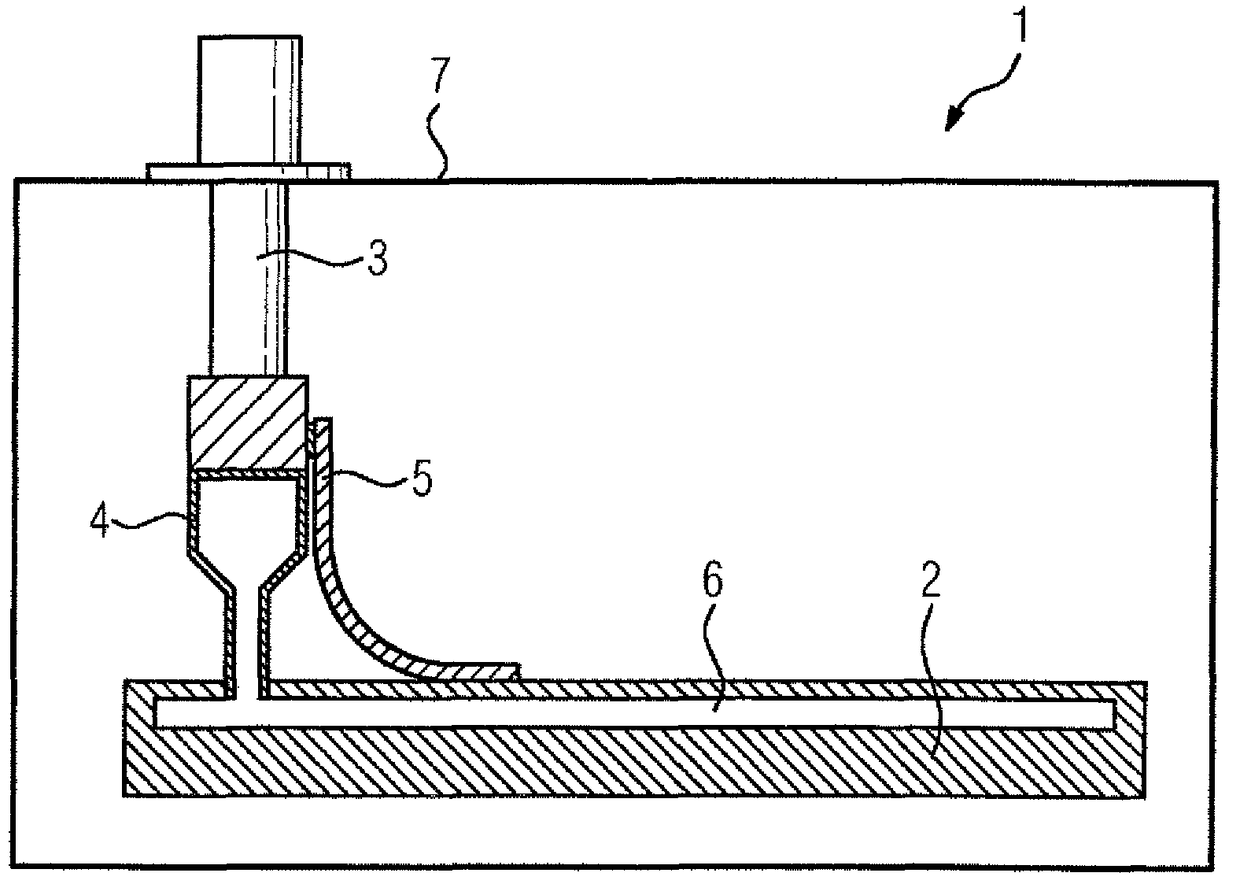
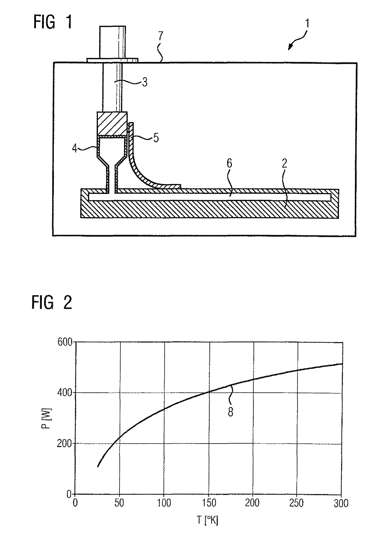
[0039]FIG. 1 shows a schematic sectional representation through an inventive device 1 for cooling a unit 2 to be cooled. The device 1 includes a cold head 3, which is thermally connected to the thermosiphon 4 by way of a condenser and to the unit 2 to be cooled by way of a mechanical heat bridge 5. In the exemplary embodiment according to FIG. 1, only a cold head 3, a mechanical heat bridge 5 and a condenser with a thermosiphon 4 are shown in each case. However the invention also includes exemplary embodiments with a number of cold heads 3 and / or a number of mechanical heat bridges 5 and / or a number of condensers with thermosiphons 4, which are not shown in the Figures for the sake of simplicity.

[0040]In FIG. 1, the cold head 3 is directly thermally and mechanically connected to the condenser 4, wherein the condenser 4 includes a thermosiphon 4. According to the thermosiphon principle, a fluid, e.g. neon, nitrogen or helium, condenses on the cold head 4 and is transported in liquid ...


PUM


Abstract

The present invention relates to a method and a device (1) for cooling an arrangement (2) using a cold head (3), with a thermal cooling of the unit (2) to be cooled by means of the thermosiphon principle. At the same time, heat is conducted via a mechanical heat bridge (5), which provides a direct thermal connection from the cold head (3) to the unit (2) to be cooled.

Description

CROSS-REFERENCES TO RELATED APPLICATIONS[0001]This application is the U.S. National Stage of International Application No. PCT / EP2012 / 065893, filed Aug. 14, 2012, which designated the United States and has been published as International Publication No. WO 2013 / 034408 and which claims the priority of German Patent Application, Serial No. 10 2011 082 352.2, filed Sep. 8, 2011, pursuant to 35 U.S.C. 119(a)-(d).BACKGROUND OF THE INVENTION[0002]The present invention relates to a method and a device for cooling a unit using a cold head, with a thermal cooling of the unit to be cooled by means of the thermosiphon principle.[0003]Cold heads are frequently used to cool units, such as for instance superconducting coils, down to low temperatures. Superconducting coils can be used for instance in magnetic spin tomography devices, in motors, in generators or in current limiters. Cooling occurs here to temperatures of below 100 K. Particularly with the use of high-temperature superconducting (HT...

Claims


Application Information

Patent Timeline
IPC IPC(8): F25D31/00F28D15/02F25D19/00H01F6/04G01R33/38F25B23/00
CPCF25D31/005F25D19/006F28D15/0266H01F6/04F28D15/0275G01R33/3804F25B23/006
Inventor SCHMIDT, HEINZ
Owner SIEMENS ENERGY GLOBAL GMBH & CO KG
Why Eureka
Try Eureka