
Mitigating interaction between adaptive equalization and timing recovery

a timing recovery and adaptive equalization technology, applied in transmission monitoring, line-fault/interference reduction, baseband system details, etc., can solve problems such as interference with the clock recovery process, system noise and timing jitter, and usually distorted phase and amplitude, so as to reduce or eliminate the interaction and preserve the ability of adaptation

Active Publication Date: 2018-11-20
MACOM CONNECTIVITY SOLUTIONS LLC
View PDF29 Cites 1 Cited by
  • Summary
  • Abstract
  • Description
  • Claims
  • Application Information

AI Technical Summary

Benefits of technology

The patent text describes a method for reducing clock delay correction in a timing recovery loop of an equalizer-based system. The method compensates for the clock delay introduced during the equalization process by adjusting the tap weights of the equalization filter. This results in a more accurate timing recovery. The method allows for the effective prevention of interaction between clock delay correction and the timing recovery loop.

Problems solved by technology

In addition, when data is transmitted over a communication channel, it is usually distorted in terms of phase and amplitude due to various types of noise, such as fading, oscillator drift, frequency and phase offset, and receiver thermal noise.
At the receiver, the system is also subject to noise and timing jitter in a time domain.
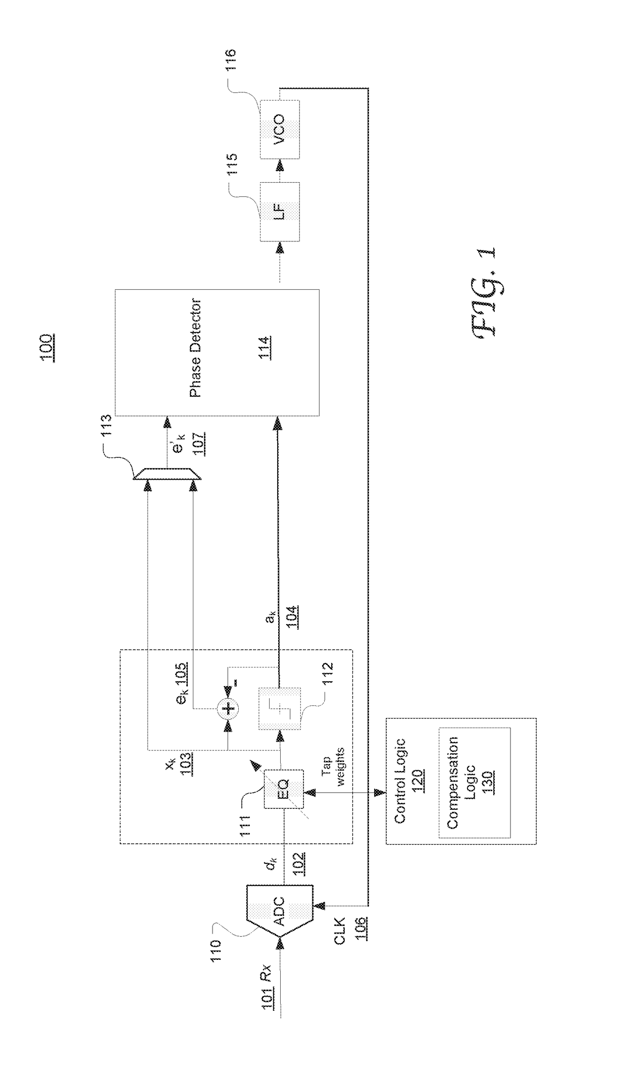
Adaptive equalization itself can also result in correction for time delays of the input clock embedded in the received signal, which undesirably interferes with the clock recovery process by the overall timing recovery loop, e.g., to be performed by a phase detector, a loop filter and a VCO in the same timing recovery loop.
Particularly, the interference may cause recovered data symbols to shift from their optimized locations.
Unfortunately, freezing or slowing down the equalizer adaptation process inevitably impairs the equalizer's capability of tracking changes in channel characteristics over time.

Method used


Image

  • Mitigating interaction between adaptive equalization and timing recovery
  • Mitigating interaction between adaptive equalization and timing recovery
  • Mitigating interaction between adaptive equalization and timing recovery

Examples


Embodiment Construction

[0012]Reference will now be made in detail to the preferred embodiments of the present invention, examples of which are illustrated in the accompanying drawings. While the invention will be described in conjunction with the preferred embodiments, it will be understood that they are not intended to limit the invention to these embodiments. On the contrary, the invention is intended to cover alternatives, modifications, and equivalents which may be included within the spirit and scope of the invention as defined by the appended claims. Furthermore, in the following detailed description of embodiments of the present invention, numerous specific details are set forth in order to provide a thorough understanding of the present invention. However, it will be recognized by one of ordinary skill in the art that the present invention may be practiced without these specific details. In other instances, well-known methods, procedures, components, and circuits have not been described in detail ...


PUM


Abstract

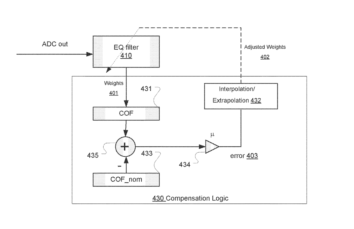
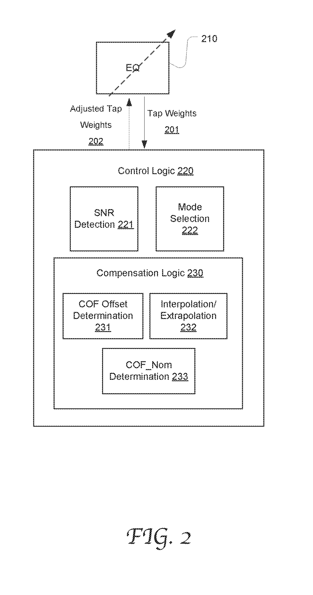
System and method of timing recovery for recovering a clock signal with reduced interference with clock phase correction by an adaptive equalizer. The equalizer in the timing recovery loop is dynamically adapted to the current channel characteristics that vary over time. The equalizer includes compensation logic operable to detect and compensate a correction of clock phase ascribed to the equalization adaptation. The compensation logic can calculate the offset between a center of filter (COF) value and a COF nominal value, the offset indicative of the amount and direction of clock phase correction contributed by the equalizer. Based on the offset, the compensation logic adjusts the equalized signal by adjusting the tap weights of the equalizer to correct the offset, thereby compensating the clock phase correction.

Description

CROSS-REFERENCE[0001]This application is related to the co-pending common-assigned U.S. patent application Ser. No. 15 / 151,154, titled “TIMING RECOVERY WITH ADAPTIVE CHANNEL RESPONSE ESTIMATION,” filed on May 10, 2016, and the co-pending common-assigned U.S. patent application Ser. No. 15 / 191,229, entitled “RESOLVING INTERACTION BETWEEN CHANNEL ESTIMATION AND TIMING RECOVERY,” filed on Jun. 23, 2016. The contents of the foregoing patent applications are herein incorporated by reference by entirety for all purposes.TECHNICAL FIELD[0002]The present disclosure relates generally to the field of signal processing in communications and, more specifically, to the field of timing recovery in signal processing.BACKGROUND OF THE INVENTION[0003]In communications systems, a transmitter sends data streams to a receiver in symbols, such as bits of data. As the receiver clock is typically not synchronized with the transmitter clock, the receiver needs to correctly recover the clock from the receiv...

Claims


Application Information

Patent Timeline
Patent Type & Authority Patents(United States)
IPC IPC(8): H04L7/04H04L27/01H04L25/03H04L7/00H04L12/26H04L25/08H04B17/336
CPCH04L7/04H04L7/0029H04L25/0307H04L27/01H04L25/03885H04L43/028H04B17/336H04L25/08H04L7/0025H04L7/0062H04L7/0037
Inventor AZENKOT, YEHUDAZEYDEL, BART R.
Owner MACOM CONNECTIVITY SOLUTIONS LLC
Learn More