
Steam-solvent-gas process with additional horizontal production wells to enhance heavy oil / bitumen recovery

a technology of solvent gas and production wells, which is applied in the direction of drilling accessories, drilling machines and methods, fluid removal, etc., can solve the problems of progressively lower sagp oil rates, and achieve the effect of increasing the temperature of the reservoir

Active Publication Date: 2018-12-04
MEG ENERGY CORP
View PDF11 Cites 5 Cited by
  • Summary
  • Abstract
  • Description
  • Claims
  • Application Information

AI Technical Summary

Benefits of technology

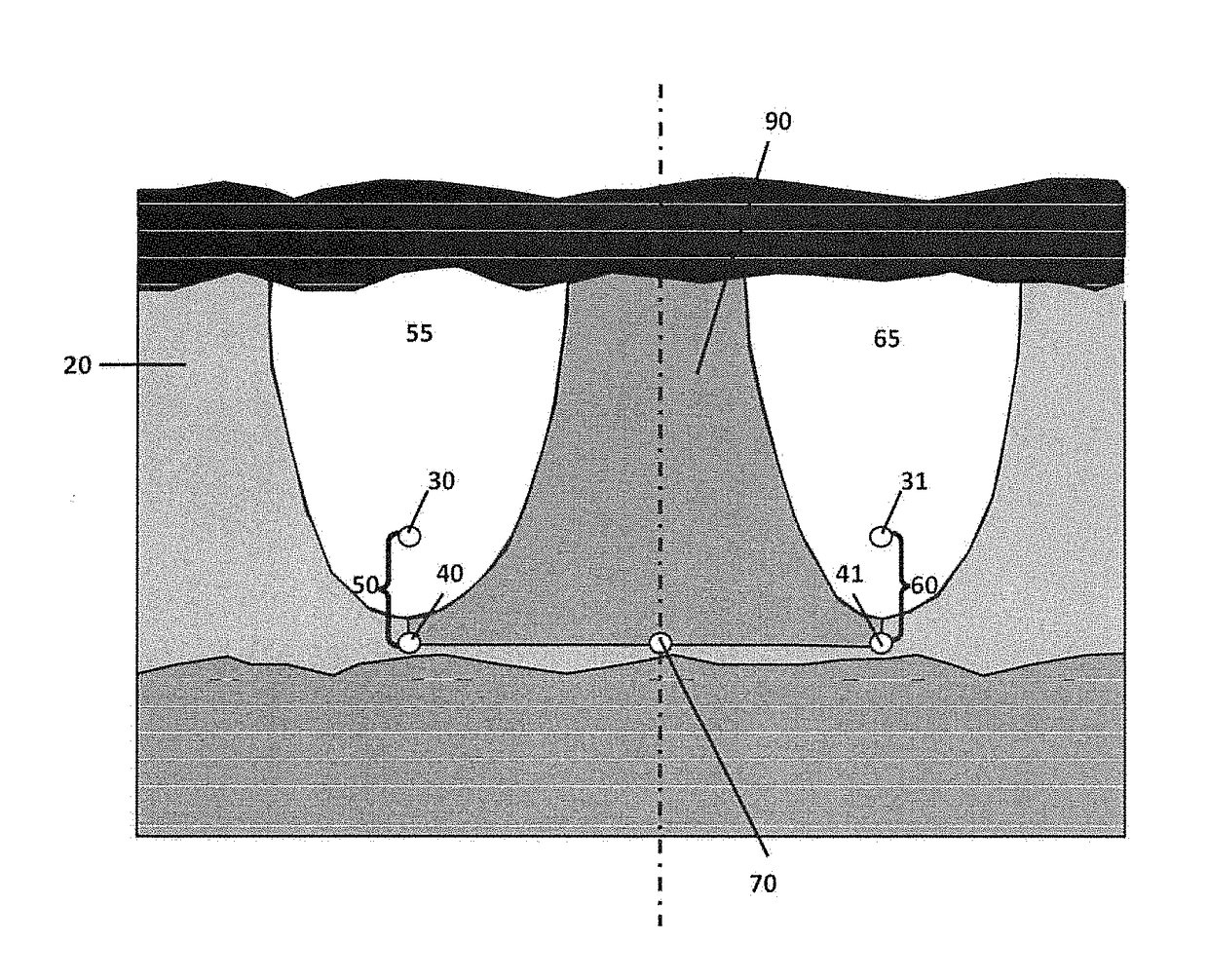
[0009]In one embodiment, the invention comprises a process for production of Oil from a reservoir where steam injection in an initial SAGD production configuration with two or more adjacent well pairs is initiated and continues until the reservoir Oil's viscosity is altered to become mobile, after which the following processes follow, in any order: (i) solvent injection into the reservoir from surface is initiated, the solvent mixing with the mobilized reservoir Oil for production as an oil phase liquid; and (ii) production from the reservoir to surface is done via at least one SAGD producer and an optional additional in-fill producer. It is to be understood that the injection of heat into the reservoir Oil may be economic where the heat injection process is not SAGD or SAGP but is another method of increasing temperature of the reservoir in situ. The process of this embodiment also contemplates, as required, co-injection through an injector of at least one SAGD well pair of additional steam to maintain or increase reservoir temperature and / or co-injection of NCG to increase or maintain reservoir pressure. It is to be understood that the injected amount of one or more of steam, solvent, NCG, heat or pressure is adjusted to optimize reservoir oil phase viscosity and chamber pressure and temperature for efficient production of reservoir Oil to surface.
[0013]The present invention makes use of the heat stored in the reservoir to improve the thermal efficiency of SAGD without requiring two adjacent SAGD chambers, to merge. The average temperature in the Oil in the space or region between the adjacent chambers may be estimated from the cumulative Oil production and steam injection. Here, when we use the term “oil phase” we use it to describe the non-aqueous, flowing, liquid phase containing Oil. Oil phase is used to distinguish this liquid from other fluids in the system such as substances which are in a gas phase, for example. As the average temperature of the Oil in the region continues to increase, the viscosity of the initially immobile Oil will be reduced to a point where it is mobile enough to be produced from the additional producer (for example) using methods that are commonly used to produce heavy oil. Being thus mobilized, the Oil is also capable of better mixing with the injected solvent. Since at this stage, the initially immobile Oil is mobile enough to be produced by conventional methods, there is no need to continue steam injection at full rates. Solvent is then injected or co-injected with reduced steam and with or without NCG, to further reduce oil phase viscosity, maintain chamber pressure, and recover the heat stored in the chambers.
[0014]The heat recovered by the solvent / NCG / reduced steam injection boils residual water in the chambers and further steam is produced in situ. The in situ generated steam flows to chamber boundaries where it condenses and transfers heat to the Oil. The steam, solvent and NCG in the chamber also provide a pressure drive to push heated solvent-rich oil phase to the additional producer. This combination of viscosity reduction by solvent dissolution, combined with the effect of heat recovery and transfer to the Oil by solvent / NCG / reduced-steam co-injection, and production via the additional producer together results in significant acceleration of the Oil rate (that is, the volume of produced Oil in the oil phase over time from the reservoir), and reductions in steam consumption and CSOR, while maintaining high recoveries similar to or better than SAGD process recoveries. Solvent injection, with or without steam / NCG co-injection, begins when sufficient heat has been stored in the region outside the steam chambers and not from the beginning of the heat injection (for instance, by initial steam injection in a SAGD process).

Problems solved by technology

However, once the chamber reaches the top of the reservoir, there is a risk that the SAGP oil rates could become progressively lower as compared to SAGD.

Method used


Image

  • Steam-solvent-gas process with additional horizontal production wells to enhance heavy oil / bitumen recovery

Examples


Embodiment Construction

[0017]SAGD may be modified by injecting a solvent, with or without steam / NCG. The SAGD well arrangement may also be modified. Solvent injection is used to decrease the viscosity of the oil phase by the solvent concentration effect, in addition to the decrease of viscosity caused by the temperature increase effect due to steam injection. Solvent / NCG injection is also used to recover the heat stored in the chamber and for pressure maintenance. The timing of injection of solvent, steam and NCG has to be chosen appropriately. A process of this type, without the solvent, is described in Canadian Patent 2776704.

[0018]The well system for a preferred embodiment of the process here is a modification of the SAGD system with additional producers. The system consists of two adjacent horizontal and essentially parallel injector-producer well pairs 50, 60, vertically separated by a short distance (typically 4-10 m), of the type used for SAGD, with an additional horizontal production well 70 (refe...


PUM


Abstract

A system and method of production of hydrocarbons, such as heavy oil or bitumen, by injection of steam, solvent and NCG is provided, which combines the benefits of SAGD, VAPEX, and the use of an additional producer, with specific timing specifications for the initiation of solvent injection prior to inter-chamber fluid communication.

Description

FIELD OF THE INVENTION[0001]This invention is related to the recovery of hydrocarbons such as heavy oil or bitumen from an underground formation (any of which hydrocarbons are referred to here as “Oil”), using a combination of steam-assisted gravity drainage, solvent injection either alone or with steam and / or non-condensable gas, and additional production wells.PRIOR ART[0002]“Steam-Assisted Gravity Drainage” or “SAGD” is the process commonly employed in commercial projects for hydrocarbon recovery from heavy oil and bitumen deposits. The SAGD process, based on Canadian Patent 1130201, makes use of a pair of essentially parallel horizontal wells, separated by a short vertical distance (typically 4-10 m), to recover immobile oil at initial reservoir conditions. Steam is injected into the oil reservoir continuously from the top horizontal well and the heated oil in the reservoir drains by gravity from the reservoir into the bottom horizontal producer well. During the start-up phase, ...

Claims


Application Information

Patent Timeline
Patent Type & Authority Patents(United States)
IPC IPC(8): E21B43/24E21B43/16E21B43/30E21B43/241E21B7/04
CPCE21B43/2408E21B43/168E21B43/241E21B43/305E21B43/24E21B7/046
Inventor YEE, CHI-TAKBHARATHA, SUBRAMANYAMMCCAFFREY, WILLIAM J.
Owner MEG ENERGY CORP
Learn More