Method and arrangement for determining the heating condition of a mirror in an optical system

Active Publication Date: 2018-12-25
CARL ZEISS SMT GMBH
View PDF67 Cites 1 Cited by
  • Summary
  • Abstract
  • Description
  • Claims
  • Application Information

AI Technical Summary

Benefits of technology

The patent aims to provide a way to determine how hot a mirror is in an optical system, specifically in a machine used for making microelectronic devices. The invention has been designed to not negatively affect the performance of the optical system and to allow for accurate identification of the heating condition.

Problems solved by technology

Mirrors are used as optical components for the imaging process in projection objectives designed for the EUV range, that is to say at wavelengths of for example about 13 nm or about 7 nm, due to the lack of availability of suitable translucent refractive materials.
A problem which arises in practice is that the EUV mirrors experience a rise in temperature and linked thereto thermal expansion or deformation, as a consequence of absorption of the radiation emitted by the EUV light source but also because of cleaning in a hydrogen atmosphere, and such expansion or deformation in turn can result in worsening of the imaging properties of the optical system.

Method used


Image

  • Method and arrangement for determining the heating condition of a mirror in an optical system
  • Method and arrangement for determining the heating condition of a mirror in an optical system
  • Method and arrangement for determining the heating condition of a mirror in an optical system

Examples


Embodiment Construction

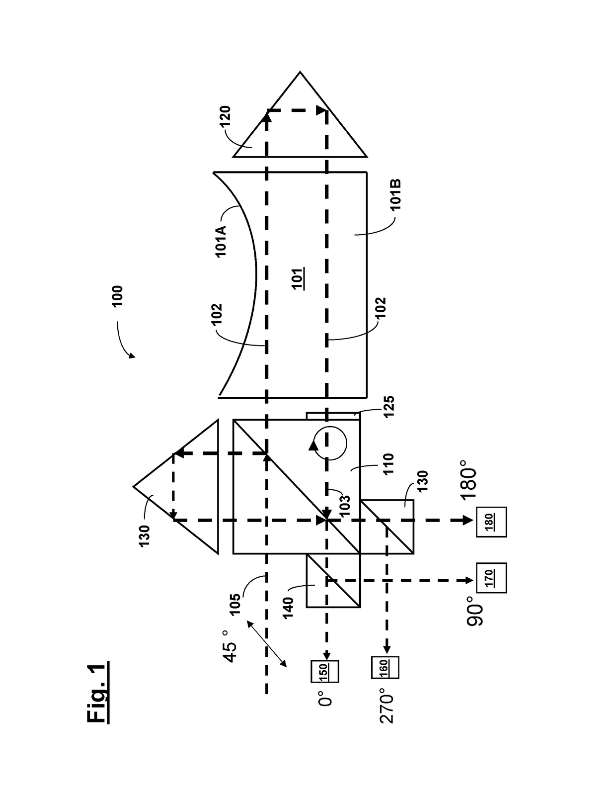
[0069]Hereinafter embodiments of the invention are described with reference to FIGS. 1 through 3, in which contact-less measurement of the temperature-induced change in refractive index is effected interferometrically, as relative and integral measurement.

[0070]A measuring arrangement 100 by way of example for temperature measurement at a mirror 101 is shown in FIG. 1.

[0071]Referring to FIG. 1 a linearly polarised laser beam 105 produced by a laser light source (not shown) is coupled into the measuring arrangement 100 and is firstly incident on a polarisation-neutral or polarisation-independent beam splitter 110. Without the invention being restricted thereto for example an infrared laser involving a wavelength of a few micrometers (μm) can be used as the measuring light source. The laser beam 105 is coupled into the measuring arrangement 100 in such a way that the polarisation direction of the light incident on the beam splitter 110 is at an angle of 45° relative to the plane defin...


PUM


Abstract

The invention concerns a method of and an arrangement for determining the heating condition of a mirror in an optical system, in particular in a microlithographic projection exposure apparatus. In an embodiment the mirror is an EUV mirror and a method according to the invention comprises the following steps: deflecting at least one input measuring beam on to the mirror; ascertaining at least one optical parameter of at least one output measuring beam produced from the input measuring beam after interaction with the mirror; and determining the heating condition of the mirror on the basis of the parameter.

Description

CROSS REFERENCE TO RELATED APPLICATIONS[0001]This application claims is a continuation of, and claims priority under 35 U.S.C. § 120 to, international patent application PCT / EP2011 / 070320, filed Nov. 17, 2011, which claims priority under 35 U.S.C. § 119 to German Patent Application DE 10 2010 061 950.7 filed on Nov. 25, 2010. International patent application PCT / EP2011 / 070320 also claims priority under 35 U.S.C. § 119(e)(1) to US patent application 61 / 417,552, filed on Nov. 29, 2010. The content of these applications is hereby incorporated by reference.FIELD OF THE INVENTION[0002]The invention concerns a method and arrangement for determining the heating condition of a mirror in an optical system, in particular in a microlithographic projection exposure apparatus.BACKGROUND[0003]Microlithography is used for the production of micro structured components such as for example integrated circuits or LCDs. The microlithography process is carried out in a so-called projection exposure appa...

Claims


Application Information

Patent Timeline
IPC IPC(8): G01K11/00G01M11/00G01J5/00G01B9/02G03F7/20G02B7/18
CPCG01K11/00G01B9/02024G01B9/02081G01M11/005G03F7/708G03F7/7085G03F7/70891G02B7/181G01B2290/70
Inventor VOGT, PETERHERMANN, MARTINDIER, OLIVERMAJOR, ANDRAS G.
Owner CARL ZEISS SMT GMBH
Why Eureka
Try Eureka