
Laser cutting head for machine tool

a cutting head and machine tool technology, applied in metal-working equipment, welding equipment, manufacturing tools, etc., can solve the problems of reducing the power available for cutting, requiring expensive gas consumption, and the external cooling of the casing containing the focusing unit is not sufficient to ensure an adequate cooling so as to prevent damage to the protective superficial layer of the focusing lens. , the effect of efficient and accurate cutting

Active Publication Date: 2019-01-08
SALVAGNINI ITAL
View PDF8 Cites 0 Cited by
  • Summary
  • Abstract
  • Description
  • Claims
  • Application Information

AI Technical Summary

Benefits of technology

The patent describes a laser cutting head with a special cooling system that prevents the focusing lens from shifting during use. This ensures that the laser beam is always focused on the workpiece surface, resulting in efficient and accurate cutting. The cooling system also prevents damage to the protective layer of the focusing lens. As a result, the invention provides a better and more reliable cutting tool for industrial applications.

Problems solved by technology

External cooling of the casing containing the focusing unit is not, in fact, sufficient to guarantee an adequate cooling of the focusing lens.
However cooling systems using a gas flow have the drawback of requiring the use of expensive gases that are devoid of contaminating elements.
Contaminating or extraneous particles or elements contained in the gas may deposit on the focusing lens, causing not only a variation of the refraction index of the optics, but also an absorption of the energy of the laser beam and hence a reduction in the power available for cutting.
Moreover, such systems are quite complex and expensive to be manufactured and require a periodical maintenance.

Method used


Image

  • Laser cutting head for machine tool
  • Laser cutting head for machine tool
  • Laser cutting head for machine tool

Examples


first embodiment

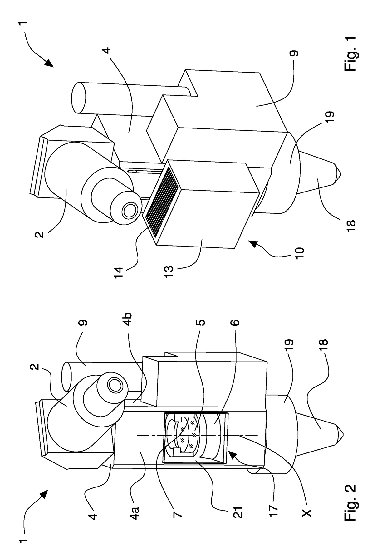
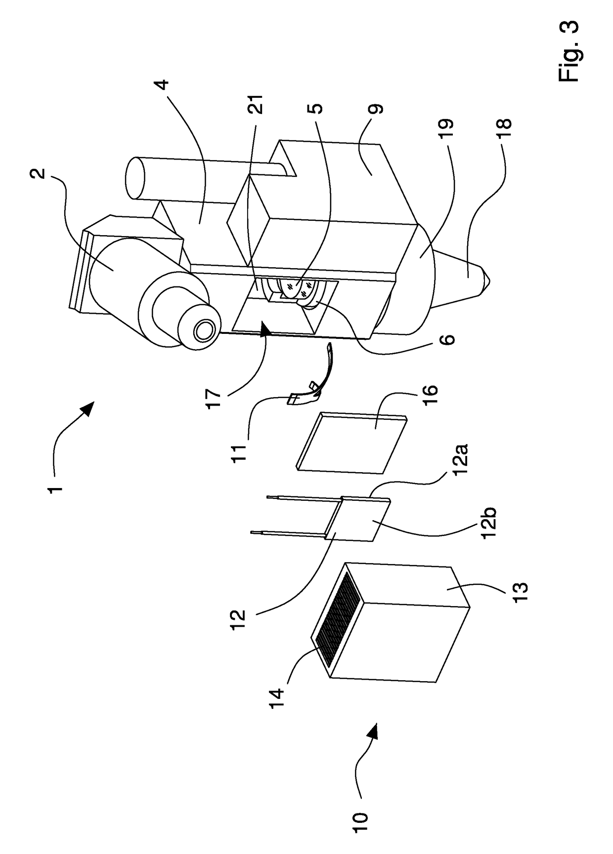
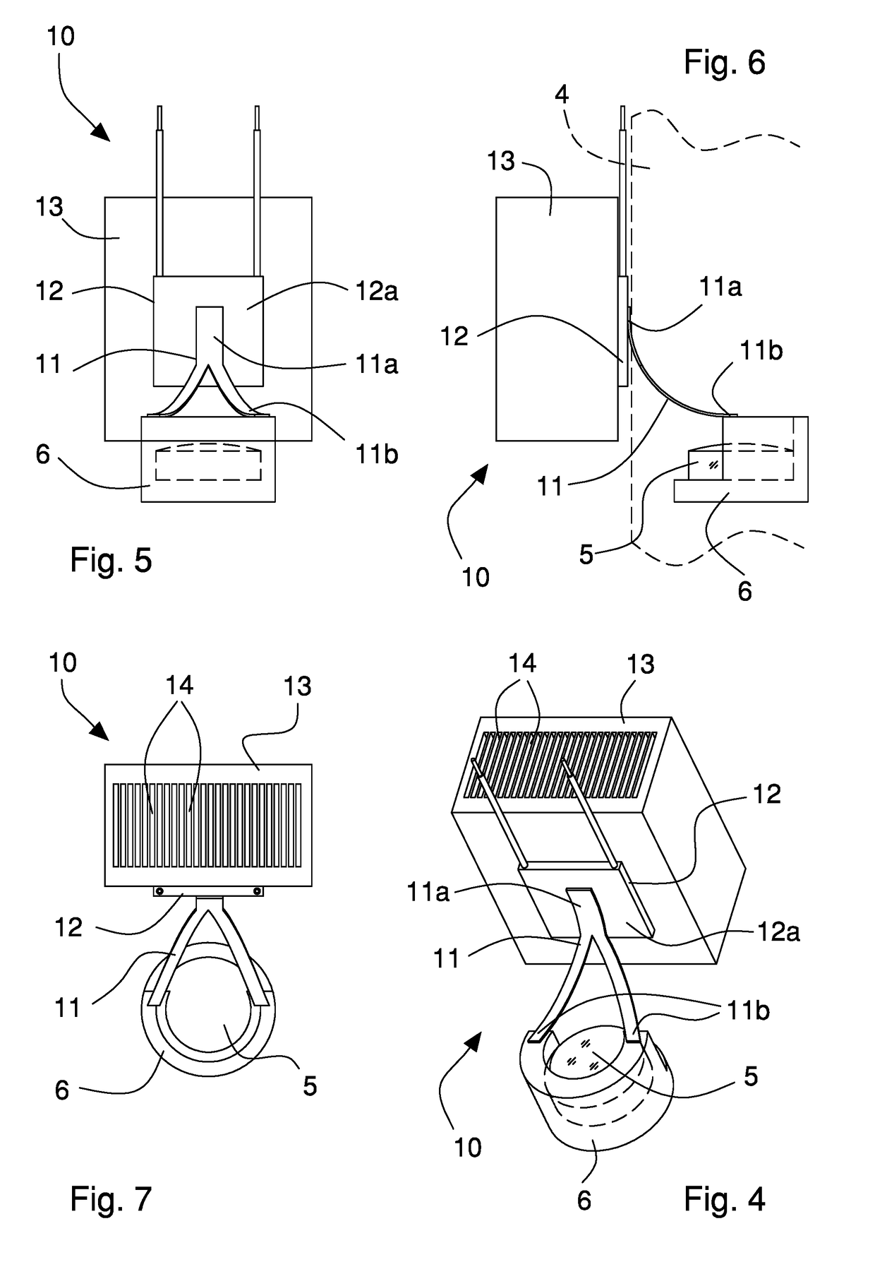
[0059]With reference to FIGS. 1 to 7, a laser cutting head 1 is shown according to the invention, which is arranged to be powered by a laser emission apparatus, of a known type and not shown in the figures, by means of optical transmission means and associable with a cutting machine tool. In particular, the emission apparatus is of solid-state laser stimulated emission type, and the optical transmission means comprises an optical fiber cable suitable for conveying the laser beam generated by the emission apparatus to the laser cutting head 1.

[0060]The laser cutting head 1 comprises collimation means 2 for collimating the laser beam generated by the laser emission apparatus, focusing means 5 for focusing the collimated laser beam leaving the collimation means 2 and a casing 4 for containing and housing the focusing means 5.

[0061]The laser cutting head 1 also comprises a cutting nozzle 18, that is fixed to the casing 4 by an optical centering ring-nut 19 and through which the focused ...

second embodiment

[0092]With reference to FIGS. 12 to 14, a laser cutting head 1 is shown according to the invention, which is arranged to be powered by a laser emission apparatus by means of optical transmission means and is associable with a cutting machine tool.

[0093]The laser cutting head 1 comprises collimation means 2 for collimating the laser beam generated by the laser emission apparatus, focusing means 5 for focusing the collimated laser beam leaving the collimation means 2 and a casing 4 for containing and housing the focusing means 5.

[0094]The laser cutting head 1 also comprises a cutting nozzle 18, that is fixed to the casing 4 for example by a ring-nut 19 and through which the focused laser beam comes out.

[0095]The collimation means 2 are of known type and may comprise a set of lenses capable of converging and collimating the laser beam coming from the optical transmission means in a rectilinear laser beam. A mirror can be provided for redirecting the laser beam towards the focusing mean...


PUM

PropertyMeasurementUnit
refractive indexaaaaaaaaaa
flexibleaaaaaaaaaa
thermal conductivityaaaaaaaaaa

Abstract

A laser cutting head powered by a laser emission apparatus includes a collimation device to collimate a laser beam coming from the laser emission apparatus and a focusing lens which focuses a collimated laser beam from the collimation device. The lens is supported in a casing and is movable along an adjustment direction to change a focal point of the laser beam. A cooling unit is connected with the casing and includes at least one Peltier cell and a heat dissipation element. A thermal conductive element connects a support for the lens with the cooling unit to extract heat generated by the laser beam passing through the lens by thermal conduction from the support and from the lens.

Description

[0001]This application is a § 371 National Stage Entry of PCT / EP2014 / 075209 filed Nov. 20, 2014. PCT / EP2014 / 075209 claims priority to EP Application No. EP13194090.0 filed Nov. 22, 2013. The entire content of these applications are incorporated herein by reference.BACKGROUND OF THE INVENTION[0002]The present invention relates to laser cutting devices for cutting machine tools and in particular relates to a laser cutting head to be used in a fiber optic laser cutting system in a cutting / punching machine tool for sheet metal.DESCRIPTION OF RELATED ART[0003]The use of laser systems for cutting, engraving and welding parts is well known and widely diffused in the field of machine tools for processing metal sheets and plates.[0004]A laser device emits a coherent, monochrome ray of light, concentrated in a rectilinear beam having extremely high luminosity (brilliance), by means of a stimulated emission process. The possibility of concentrating a large amount of energy in a very small poin...

Claims


Application Information

Patent Timeline
Patent Type & Authority Patents(United States)
IPC IPC(8): B23K26/02B23K26/38B23K26/046B23K26/06B23K26/14B23K26/70B23K26/064
CPCB23K26/38B23K26/046B23K26/707B23K26/1462B23K26/703B23K26/0648G03B30/00B23K26/70B23K26/08
Inventor GESUITA, ENZOMANZO, RICCARDOGRANZIERO, ANGELO
Owner SALVAGNINI ITAL
Learn More