
Light diffusing sheet

a technology of light diffusion and light, applied in the field of light diffusion sheets, can solve the problems of difficult fine control of size, high cost, and high cost of achieve the effect of reducing time and cost and manufacturing with a relatively simple method

Active Publication Date: 2019-01-22
LEE HYUNGSUK
View PDF13 Cites 0 Cited by
  • Summary
  • Abstract
  • Description
  • Claims
  • Application Information

AI Technical Summary

Benefits of technology

The invention provides a light diffusing sheet that can be made easily and without the need for expensive methods like molding or heat treatment. This saves time and money when manufacturing lighting or display devices. The technical effect is a simpler and less expensive way to make a light diffusing sheet.

Problems solved by technology

However, such processes for manufacturing fine patterns may entail problems such as expensive equipment and long process times. The level of productivity achieved with these methods is extremely low.
However, with wet etching methods, it may be more difficult to finely control the size compared to dry etching methods such as reactive ion etching (RIE), and there is also the drawback of high unit cost associated with preparing molds for various patterns.
Moreover, although methods that do not require photolithography apparatus, such as those using nanoimprinting, microcontact printing using PDMS, and capillary lithography, may be useful for the mass-duplication of one type of fine pattern, these methods entail the difficulty of having to newly fabricate basic design molds when changing the type of pattern is necessary.

Method used


Image

  • Light diffusing sheet
  • Light diffusing sheet
  • Light diffusing sheet

Examples


example 1

Range of Tensile Strength for Pattern Forming

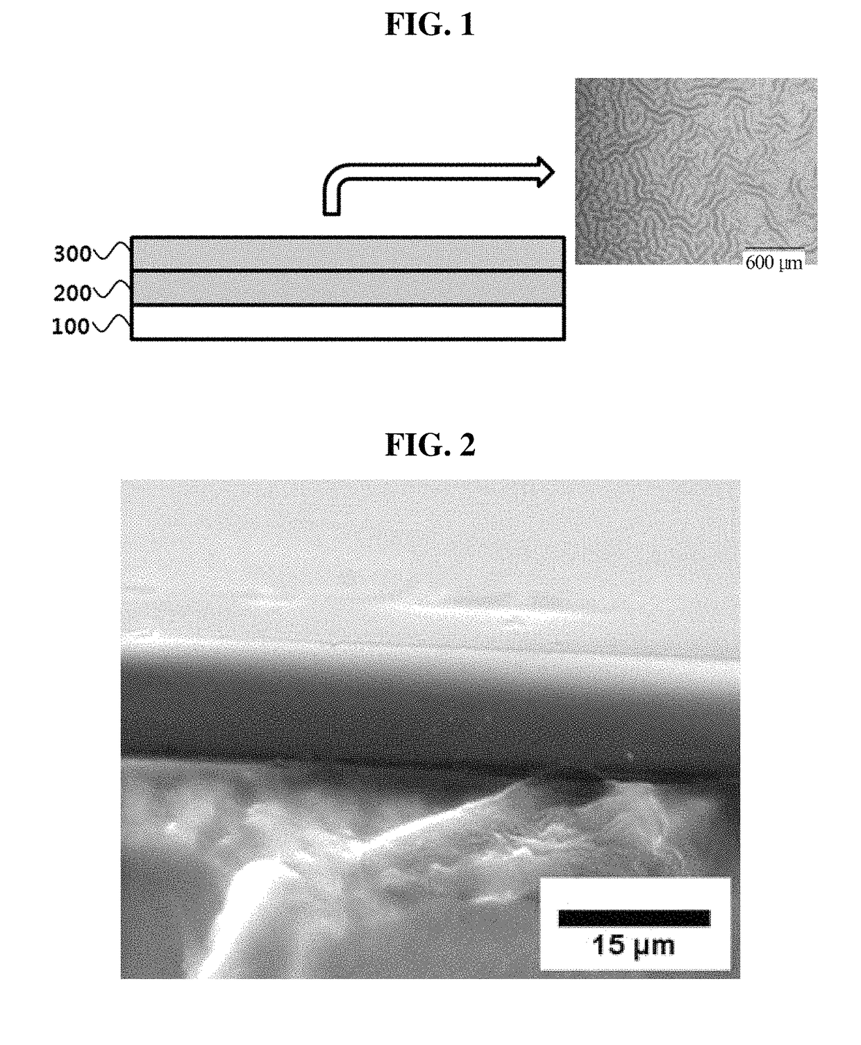
[0046]A light diffusing sheet according to an embodiment of the invention may have a pattern formed on the poly-chloro-p-xylene coating layer 300 as the poly-chloro-p-xylene coating layer 300 is formed over the PDMS coating layer 200. In order for a pattern to be formed thus, the condition that tensile strength of the PDMS coating layer 200 be 10˜60 psi must be satisfied, as described above.

[0047]When the poly-chloro-p-xylene coating layer 300 is deposited over the PDMS coating layer 200, a change occurs due to a physical force at the interface between the two polymer substances. In the poly-chloro-p-xylene coating layer 300, a compressive force occurs which affects the interface, where the compressive force causes the PDMS coating layer 200 together with the poly-chloro-p-xylene coating layer 300 to form wrinkles of a certain pattern.

[0048]In other words, the compressive force may become the driving force forming the pattern on the poly-...

example 2

Adjustment of Pattern Width

[0060]The greater the thickness of the poly-chloro-p-xylene coating layer 300, the greater may be the pattern width of the poly-chloro-p-xylene coating layer 300.

[0061]It is deemed that the change in the poly-chloro-p-xylene coating layer 300 caused by the force physically applied on the interface between the PDMS coating layer 200 and the poly-chloro-p-xylene coating layer 300 is affected up to a surface having a particular thickness, and that the compressive force of the poly-chloro-p-xylene is also strongly applied between polymer chains. That is, it is understood that the cross linking between polymer chains may be affected by the physical change at the interface, and this in turn may have an effect that reaches up to the upper surface.

[0062]This can be observed from FIG. 6A, FIG. 6B, FIG. 6C and FIG. 7 associated with Example 2.

[0063]AFM images were taken of the surface of the poly-chloro-p-xylene coating layer 300, using samples having the dimensions...


PUM

PropertyMeasurementUnit
tensile strengthaaaaaaaaaa
thicknessaaaaaaaaaa
widthaaaaaaaaaa

Abstract

A light diffusing sheet according to an embodiment of the invention may be a light diffusing sheet that is formed on one side of a substrate and has a particular pattern formed on a surface thereof, where the light diffusing sheet may include a polydimethylsiloxane (PDMS) coating layer that is formed on one side of the substrate and a poly-chloro-p-xylene coating layer that is formed on one side of the polydimethylsiloxane (PDMS) coating layer with a pattern formed on its surface, the tensile strength of the polydimethylsiloxane (PDMS) coating layer is 10 to 60 psi, and a compressive force is applied on the polydimethylsiloxane (PDMS) coating layer when an interface is formed between the polydimethylsiloxane (PDMS) coating layer and the poly-chloro-p-xylene coating layer.

Description

CROSS-REFERENCE TO RELATED APPLICATIONS[0001]This application is a Continuation Application of PCT International Application No. PCT / KR2016 / 007982, which was filed on Jul. 22, 2016, and which claims priority from Korean Patent Application No. 10-2015-0105697 filed with the Korean Intellectual Property Office on Jul. 27, 2015. The disclosures of the above patent applications are incorporated herein by reference in their entirety.BACKGROUND[0002]1. Technical Field[0003]The present invention relates to a light diffusing sheet, more particularly to a light diffusing sheet that includes an organic polymer layer.[0004]2. Description of the Related Art[0005]Research efforts in recent times are focusing more on fine pattern manufacturing, rather than on existing photolithography processes, with the aim of manufacturing fine patterns in the order of micrometers or even nanometers.[0006]In particular, since smaller sizes and high levels of integration of devices in semiconductor processes can...

Claims


Application Information

Patent Timeline
Patent Type & Authority Patents(United States)
IPC IPC(8): G02B5/02C09D165/04C09D183/04
CPCG02B5/0221G02B5/02C09D183/04C09D165/04C08G61/025C08G77/04C08G2261/11C08G2261/146C08G2261/3424
Inventor LEE, HYUNGSUK
Owner LEE HYUNGSUK
Learn More