Optical coherent receiver with forward error correction

a forward error correction and optical coherent technology, applied in the field of communication networks, can solve the problems of short transmission length, and achieve the effect of minimizing waste of resources and convenient operation

Active Publication Date: 2019-01-29
ALCATEL LUCENT SAS
View PDF16 Cites 0 Cited by
  • Summary
  • Abstract
  • Description
  • Claims
  • Application Information

AI Technical Summary

Benefits of technology

[0019]On the other hand, the inventors have noticed that a trend in devices for optical coherent transmission is that of providing them with more and more flexibility, meaning that a same device shall be capable of being easily configured to operate in different conditions. In particular, the matching between DPSs and FEC decoders shall be easily reconfigurable, according to the spectral efficiency of the modulation constellation used by the DSP block(s). Indeed, in order to increase the number of separate client channels that may be carried by a single optical carrier (namely, a single wavelength) the spectral efficiency shall be increased by using more complicated modulation schemes. However, more complicated modulation schemes result in shorter transmission lengths.
[0023]In particular, it is an object of the present invention to provide an optical coherent receiver which is flexible in that it may be easily configured to operate in different scenarios (in particular, with different number of client channels) even when it is implemented as a single, monolithic device and which—when the actual number of client channels is below the maximum one which the receiver may support—may be operated so that the waste of resources in minimized.

Problems solved by technology

However, more complicated modulation schemes result in shorter transmission lengths.

Method used


Image

  • Optical coherent receiver with forward error correction
  • Optical coherent receiver with forward error correction
  • Optical coherent receiver with forward error correction

Examples


first embodiment

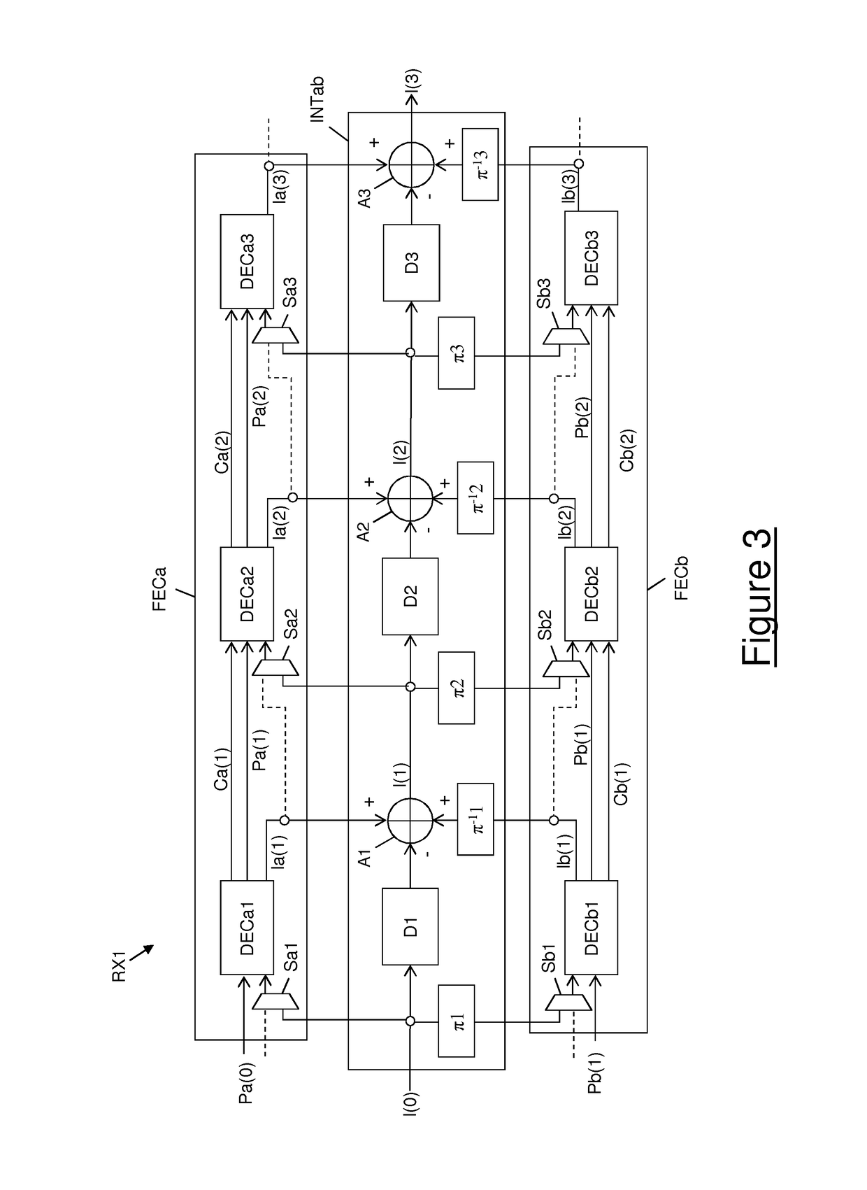
[0061]FIG. 1 shows a portion of an optical coherent receiver RX1 according to the present invention.

[0062]The portion of optical coherent receiver RX1 shown in FIG. 1 comprises a number of DSP blocks (not shown for simplicity) and a number M of FEC decoding chains. For not overloading the drawing, in FIG. 1 only two decoding chains FECa and FECb are shown. In general, however, the number M of decoding chains comprised in the optical coherent receiver RX1 is equal to the maximum number of client channels which the receiver RX1 shall be able to receive and process. For instance, if the receiver RX1 shall be able to receive and process at most 10 client channels, the number M of FEC decoding chains is 10. Preferably, the number M of FEC decoding chains is an even number equal to or higher than 2.

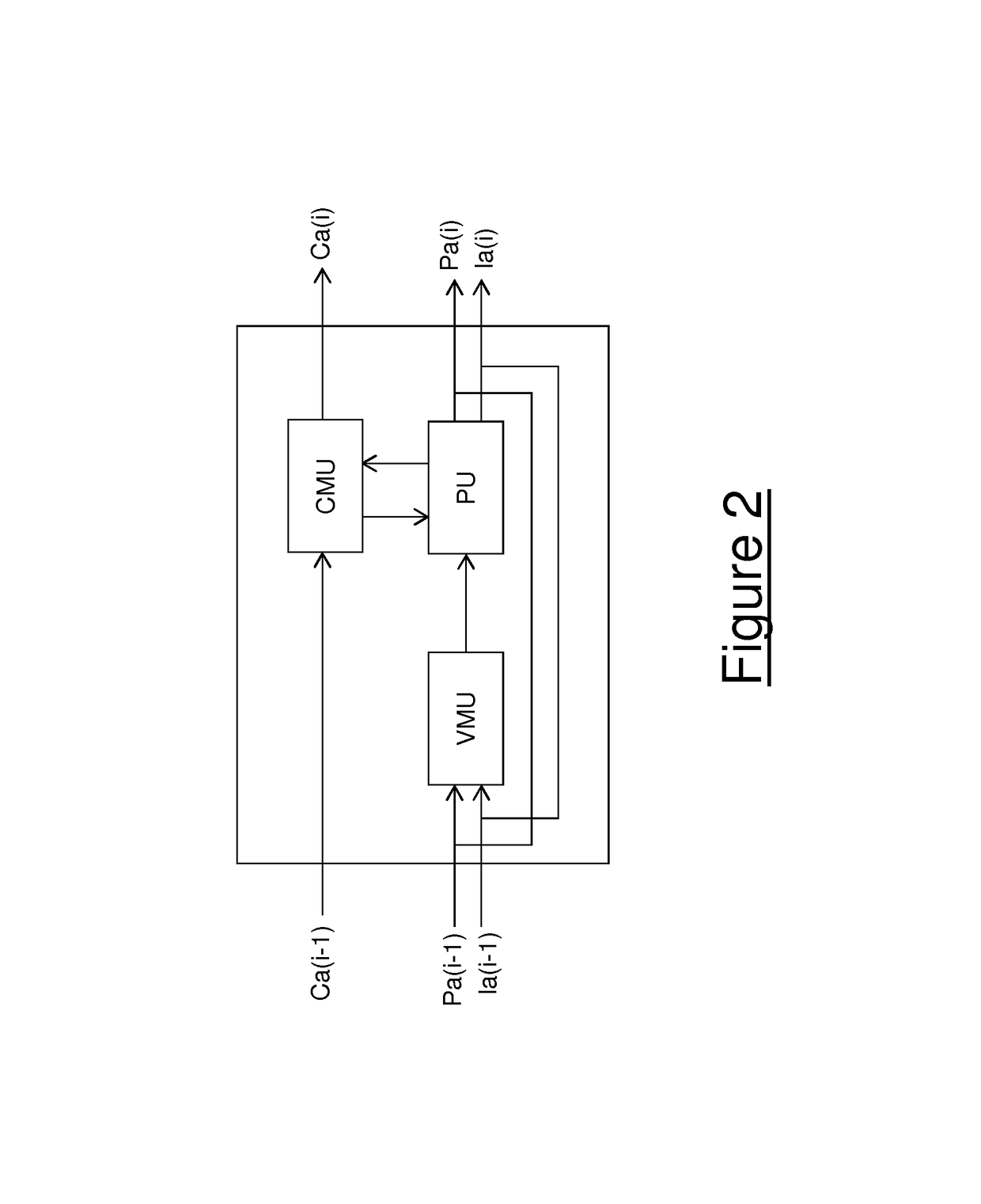
[0063]Each FEC decoding chain FECa, FECb is preferably configured to implement an iterative, soft FEC decoding algorithm on a respective client channel, as described above. In particular, each ...

second embodiment

[0133]FIG. 4 shows an optical coherent receiver RX2 according to the present invention.

[0134]According to the second embodiment, the FEC decoding algorithm implemented by each FEC decoding chain preferably provides, as an output of each iteration, only the extrinsic probabilities of the codeword bits, instead of their whole a posteriori probabilities (which also take into account the a priori probabilities). Hence, the states lea(i), leb(i) of the variable nodes corresponding to the message bits at the output of each iteration (both in the first operating mode and in the second operating mode) only comprises the extrinsic probabilities of the message bits, namely:

[0135]∑C⁢Lea⁡(1)VC[7⁢a]∑C⁢Leb⁡(1)VC[7⁢b]

[0136]Hence, the merged state I(i) provided at each iteration of the algorithm in the second operating mode of the receiver RX2 comprises a posteriori probabilities of the message bits which are calculated, for each message bit, as the sum of its a priori probability, its extrinsic pr...

third embodiment

[0140]FIG. 5 shows an optical coherent receiver RX3 according to the present invention.

[0141]Also according to the third embodiment, the FEC decoding algorithm implemented by each FEC decoding chain preferably provides, as an output of each iteration, only the extrinsic probabilities of the codeword bits. It shall be noticed however that, differently from the second embodiment of FIG. 4, the intermediate circuit of FIG. 5 guarantees that each decoding block receives at its message input the non-scaled, original extrinsic information which has been generated by the preceding decoding block. This allows preserving consistency between the states of the various variable nodes and check nodes, so as to avoid that the algorithm diverges.

[0142]The switches suitable for switching the receiver between the first and second operating mode are not shown in FIG. 5, for simplicity. The receiver is shown in FIG. 5 in its second operating mode.

[0143]This third embodiment exhibits the same advantage...


PUM


Abstract

It is disclosed an optical coherent receiver comprising a number of decoding blocks configured to implement iterations of a FEC iterative message-passing decoding algorithm. The decoding blocks are distributed into two (or more) parallel chains of cascaded decoding blocks. The receiver also comprises an intermediate circuit interposed between the two parallel chains. The optical coherent receiver is switchable between (i) a first operating mode, in which the intermediate circuit is inactive and the two parallel chains separately implement the FEC message-passing decoding algorithm on respective client channels; and (ii) a second operating mode, in which the intermediate circuit is active and the two parallel chains jointly implement the FEC message-passing decoding algorithm on a same client channel, by cooperating through the intermediate circuit.

Description

TECHNICAL FIELD[0001]The present invention generally relates to the field of communication networks. In particular, the present invention relates to an optical coherent receiver provided with a Forward Error Correction (FEC) mechanism.BACKGROUND ART[0002]As known, Forward Error Correction (FEC) is a technique for detecting and possibly correcting errors in digital data transmissions between network elements of a digital communication network, e.g. a Wavelength Division Multiplexing (WDM) communication network.[0003]According to FEC, at the transmitting side the digital data to be transmitted are encoded using an error correcting code which adds redundancy. At the receiving side, the redundancy is used to detect, and possibly to correct, errors in the original data.[0004]Different types of error correcting codes are known, including block codes and convolutional codes. In particular, in block codes the digital data to be transmitted are divided into fixed-size blocks of k message sym...

Claims


Application Information

Patent Timeline
Patent Type & Authority Patents(United States)
IPC IPC(8): H03M13/11H03M13/29H04L1/00H03M13/37H03M13/00H04B10/61
CPCH03M13/1111H03M13/1145H03M13/2963H03M13/2987H04L1/0057H03M13/6561H04B10/616H04L1/005H03M13/3746
Inventor RAZZETTI, LUCAGAVIOLI, GIANCARLOCONSTANTINI, CARLOPEPE, MARIANNA
Owner ALCATEL LUCENT SAS
Why Eureka
Try Eureka