
Engine temperature control system

a technology of engine temperature control and control system, which is applied in the direction of lubrication temperature control, machines/engines, mechanical equipment, etc., can solve the problems of increased fuel consumption, increased emissions, and reduced engine life,

Active Publication Date: 2019-02-12
TESLOVICH DARIUS
View PDF31 Cites 9 Cited by
  • Summary
  • Abstract
  • Description
  • Claims
  • Application Information

AI Technical Summary

Benefits of technology

This patent describes temperature control systems for engines. The systems include a coolant storage vessel with a heater and a control system that activates the heater when the coolant is below a certain temperature and deactivates it once the coolant has reached a certain threshold. Another example of the system includes a lubricant cooling reservoir and a pump that directs engine coolant to the resvoir based on the temperature of the lubricant. The control system monitors the temperature of the lubricant and adjusts the power supplied to the pump accordingly. Additionally, there are methods of controlling temperature by heating the engine fluid, monitoring its temperature, and then discontinuing heating when it reaches a certain threshold. The methods also involve adjusting the quantity of engine coolant supplied to the position within thermal communication with the engine fluid based on the deviation of its temperature from a predetermined threshold. Overall, these systems and methods help to maintain the optimal temperature of engine fluids to improve engine performance and reliability.

Problems solved by technology

These fluids perform best within a certain temperature range, and temperatures above or below that range can lead to increased emissions, increased fuel consumption, degradation of the fluids, and decreased engine life.

Method used


Image

  • Engine temperature control system
  • Engine temperature control system
  • Engine temperature control system

Examples


Embodiment Construction

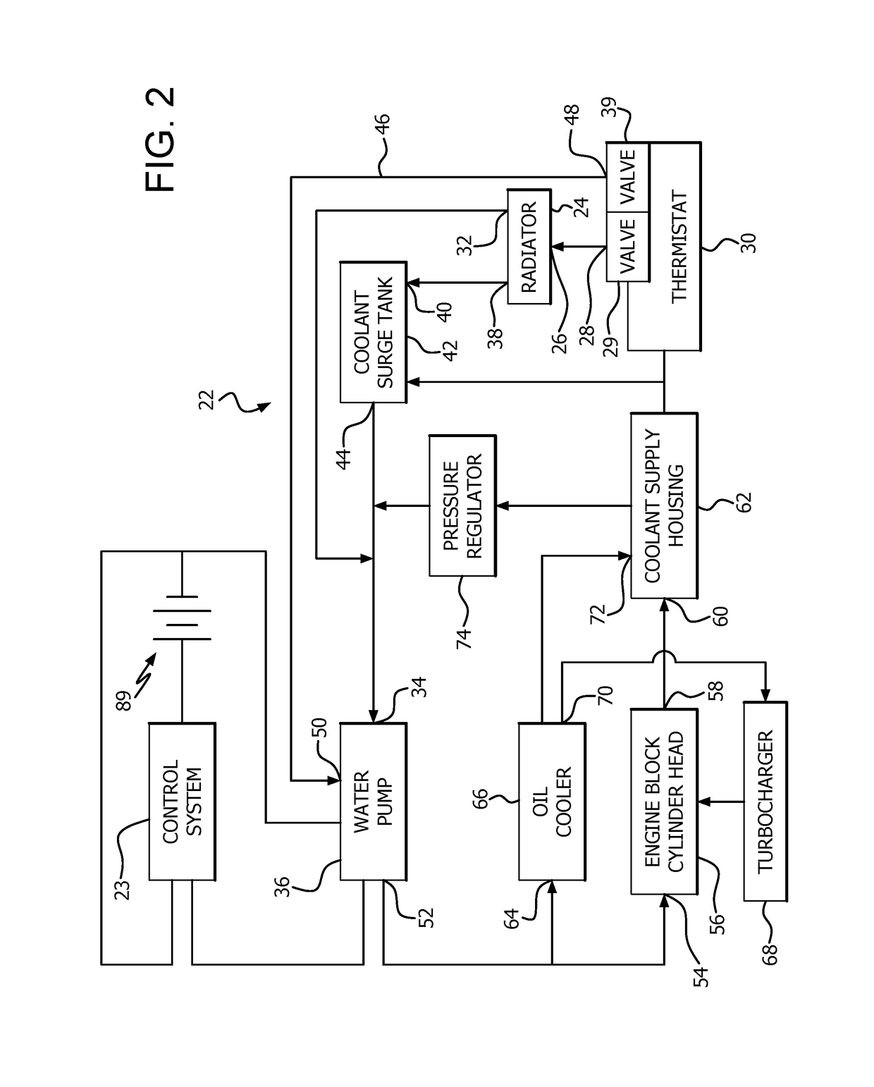
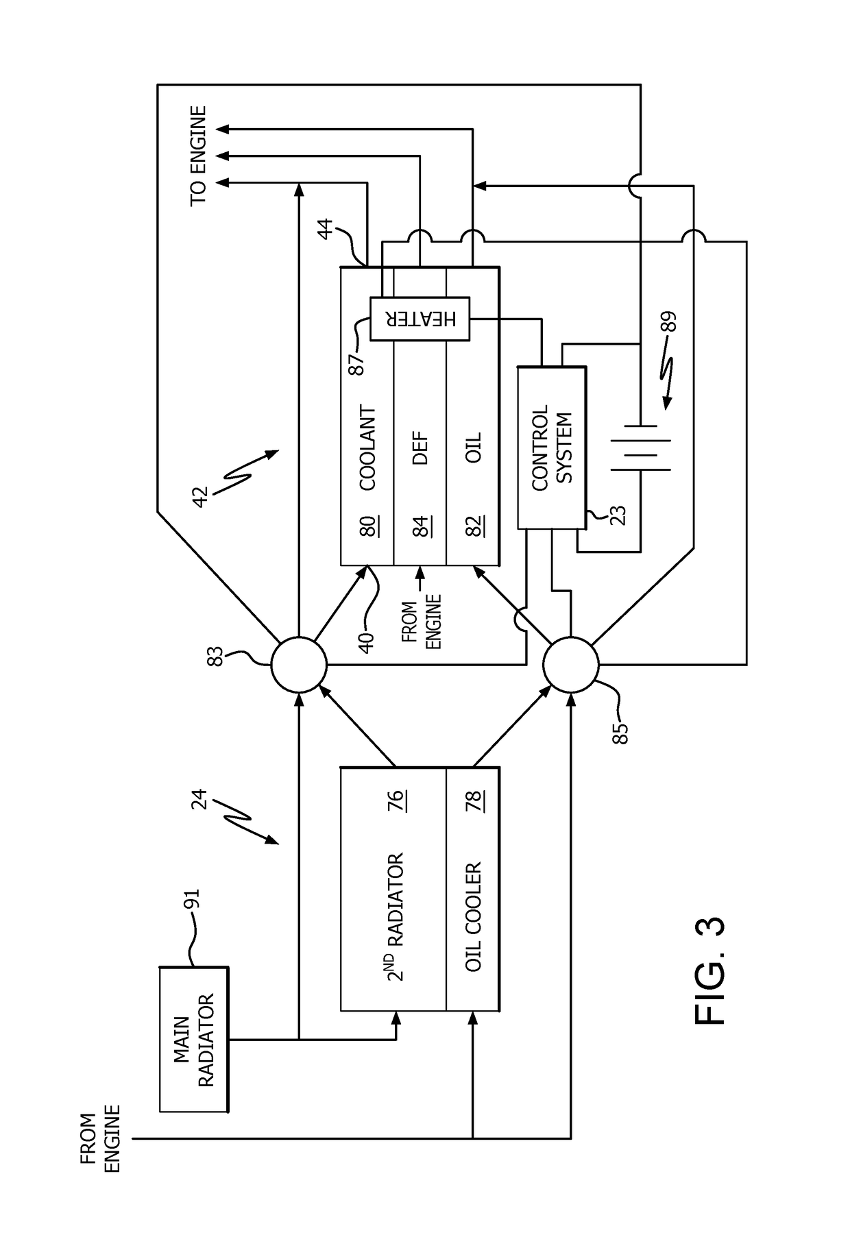
[0013]Referring to the drawings, a temperature control system is illustrated. Some examples of the temperature control system serve not only as cooling systems but also as heating systems. Engine oil operates most efficiently and effectively at a temperature range of 180° F. to 185° F. Additionally, maintaining motor oil within this temperature range will resist oxidation and nitration. For diesel engines, diesel exhaust fluid freezes at 12° F., making the fluid useless until it becomes warm enough to melt. Thus, a temperature control system that reduces the time required to reach this temperature range, and then maintains this temperature range, is advantageous for an internal combustion engine. Cold engines provide poor air emissions. Excessive heat within the exhaust also increases emission pollution as well as contributing to premature exhaust component failures.

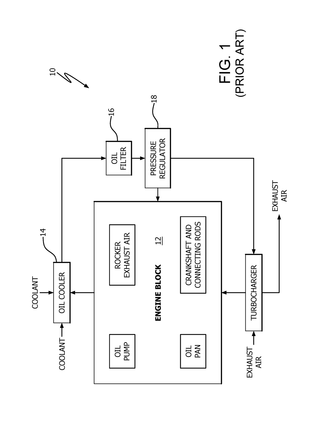
[0014]FIG. 1 illustrates the standard manner in which a turbocharger is cooled. Oil from the engine block 12 is taken ...


PUM


Abstract

An engine temperature control system is provided for heating and / or cooling engine fluids to resist deviation of the temperature of these fluids from a temperature range wherein optimal fluid performance is achieved. Some examples of the temperature control system provide for preheating fluids such as coolant, lubricant, or diesel exhaust fluid prior to starting the engine. Other examples of the temperature control system provide for improved cooling of lubricants utilized for high heat generating components such as turbochargers, continuing cooling of these fluids after the engine is stopped.

Description

CROSS REFERENCE TO RELATED APPLICATION[0001]This application claims the benefit of U.S. provisional patent application Ser. No. 62 / 156,208, filed May 2, 2015, and entitled “Engine Temperature Control System.”TECHNICAL FIELD[0002]The present invention relates to engine temperature control systems and methods. More specifically, systems and methods of optimizing the temperature of various fluids within an internal combustion engine are provided.BACKGROUND INFORMATION[0003]Internal combustion engines rely on fluids for multiple functions within the engine, including combustion, cooling, lubrication, and emissions control. These fluids perform best within a certain temperature range, and temperatures above or below that range can lead to increased emissions, increased fuel consumption, degradation of the fluids, and decreased engine life. Diesel exhaust fluid performs best above 78° F., and oil performs best above 180° F. Oil will also degrade when it becomes too hot, as can occur when ...

Claims


Application Information

Patent Timeline
Patent Type & Authority Patents(United States)
IPC IPC(8): F02B29/04F01P3/00F02B33/00F01P5/12F01P11/16F01P1/06F01P7/14F01P7/16F01P3/12F01P3/02F01N3/20F01P11/08F01M5/00
CPCF01P5/12F01P11/16F01P7/165F01P11/08F01M5/007F01N3/2066F01P3/02F01P3/12F01N2610/105F01P2003/021F01N2610/02F01N2900/1811F01P3/20F01P2005/125F01P2031/30F01P2025/08
Inventor TESLOVICH, DARIUS
Owner TESLOVICH DARIUS
Learn More