Thermal spray material and thermal spray coated article
a technology of thermal spray coating and thermal spray material, which is applied in the direction of coating, molten spray coating, metallic material coating process, etc., can solve the problems of undesirable presence of rare earth element oxide in thermal spray coating, impeded decomposition to rare earth element oxide due to thermal spraying, etc., to improve plasma erosion resistance and dusting resistance, excellent effect of plasma erosion resistan
- Summary
- Abstract
- Description
- Claims
- Application Information
AI Technical Summary
Benefits of technology
Problems solved by technology
Method used
Image
Examples
examples 1 and 2
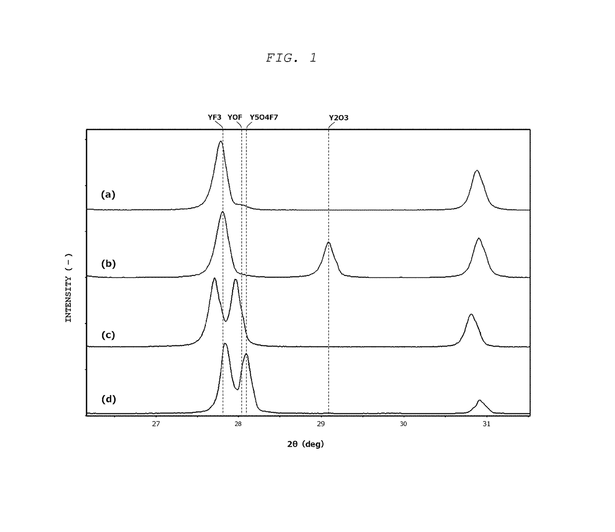
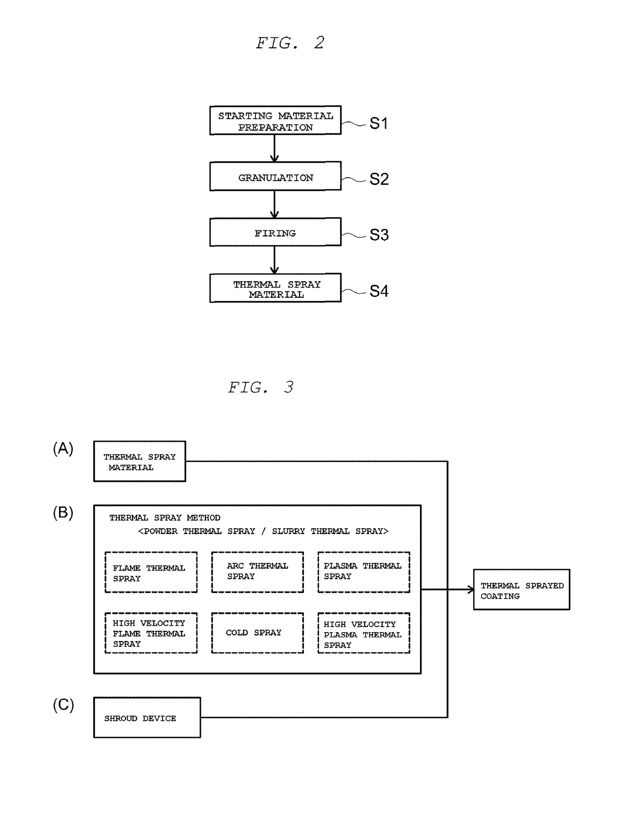
[0124]For the thermal spray materials, granular powders were prepared of yttrium oxide (Y2O3) and of yttrium fluoride (YF3), which are commonly used as protective coatings for members in semiconductor device fabrication equipment, and these were used, respectively, as the thermal spray materials in Examples 1 and 2. These materials were prepared as follows: a powder of Y2O3 or YF3 having an average particle diameter of approximately 3 μm was used as the starting material; this was dispersed in a dispersion medium along with a resin binder at a solids concentration of 50 mass %; granulation was subsequently carried out using a rotating disk-type spray-dry granulator; and sintering was performed at 1,000° C. in a nonoxidizing atmosphere.
examples 3 and 4
[0125]A yttrium oxyfluoride granular powder having the composition YOF (which was Y2O2F2) and a yttrium oxyfluoride granular powder having the composition Y5O4F7 were prepared and used as the thermal spray materials in Examples 3 and 4, respectively. These thermal spray materials were prepared as follows: powders of Y2O3 and YF3 having an average particle diameter of approximately 3 μm were used as the starting materials; these were blended to provide a YF3 proportion of approximately 40 mol % or approximately 50 mol %, respectively; and granulation and sintering were carried out under the same conditions as in Examples 1 and 2.
example 5
[0126]A powder (not granular) of a yttrium oxyfluoride having the composition Y5O4F7 was prepared and was used as the thermal spray material of Example 5. This thermal spray material was produced using the following procedure. Thus, using powders of Y2O3 and YF3 having an average particle diameter of approximately 3 μm as the starting materials, these were first blended to provide a YF3 proportion of approximately 50 mol % and a slurry was prepared by dispersion in a dispersion medium along with a resin binder. Preparation was then carried out by granulating this slurry by a spray drying procedure using an ultrasound sprayer followed by thoroughly melting or sintering at 1,000° C. in a nonoxidizing atmosphere.
PUM
| Property | Measurement | Unit |
|---|---|---|
| particle diameter | aaaaa | aaaaa |
| particle diameter | aaaaa | aaaaa |
| pore radii | aaaaa | aaaaa |
Abstract
Description
Claims
Application Information
 - R&D
- Intellectual Property
- Life Sciences
- Materials
- Tech Scout
- Unparalleled Data Quality
- Higher Quality Content
- 60% Fewer Hallucinations
Browse by: Latest US Patents, China's latest patents, Technical Efficacy Thesaurus, Application Domain, Technology Topic, Popular Technical Reports.
© 2025 PatSnap. All rights reserved.Legal|Privacy policy|Modern Slavery Act Transparency Statement|Sitemap|About US| Contact US: help@patsnap.com


