

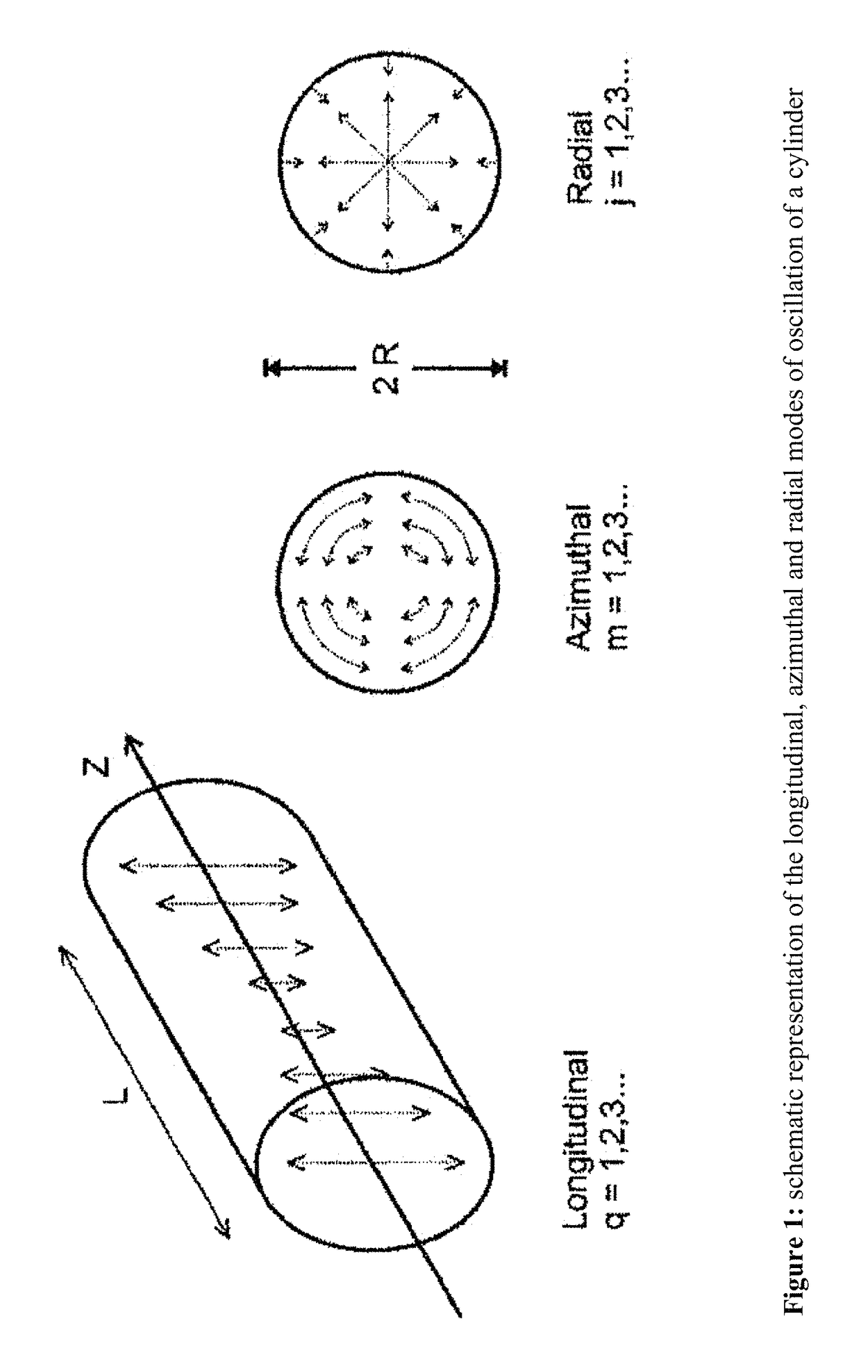
Azimuthally oscillating membrane emulsification for controlled droplet production
a technology of azimuth oscillating membrane and emulsification system, which is applied in the direction of flow mixers, mixers, mixing methods, etc., can solve the problems of limited use of this particular me technique, poor control of the droplet size distribution, and other consequences of mechanically driven membranes, etc., to achieve easy integration, high production rate, and easy process automation
- Summary
- Abstract
- Description
- Claims
- Application Information
AI Technical Summary
Benefits of technology
Problems solved by technology
Method used
Image

Examples
Embodiment Construction
Materials
[0054]The oil in water (o / w) emulsions were produced using 2 w / w Tween 20 (polyoxyethylene sorbitan monolaurate, Sigma Aldrich, UK) in distilled water as the continuous phase and food grade sunflower oil as the dispersed phase. The reported value of the interfacial tension for this system is 0.004 N m−1, and the measured viscosities for 2 w / w Tween 20 solution in water and sunflower oil are 0.001 and 0.039 Pa s, respectively.
Setup
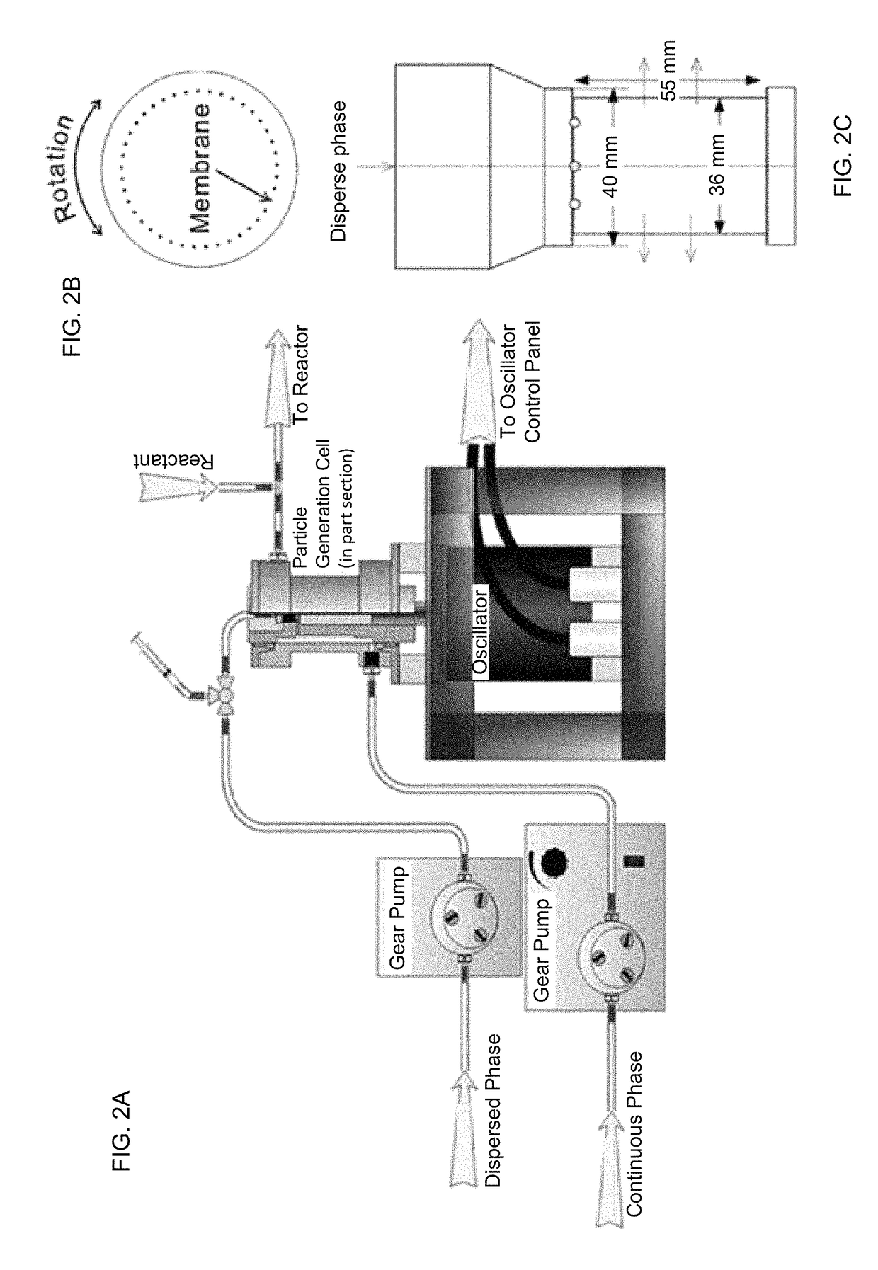
[0055]The o / w emulsions were obtained using an azimuthally oscillating membrane system (AOME) illustrated in FIG. 2A-C (Micropore Technologies Derbyshire, UK). The dispersed and continuous phases were injected using gear pumps (Ismatec®, IDEX Health & Science, Wertheim, Germany). The oscillation signal was provided by a control panel which was connected to the oscillator motor providing separate control over the frequency and membrane displacement (defined as being the peak to peak distance in the cycle and, therefore, twice the amplitude of the os...
PUM
| Property | Measurement | Unit |
|---|---|---|
| diameter | aaaaa | aaaaa |
| diameter | aaaaa | aaaaa |
| distance | aaaaa | aaaaa |
Abstract
Description
Claims
Application Information