Motor housing with electronic housing both having vertical partial cooling ribs for wet-running motor for a centrifugal pump

a technology of electronic housing and motor housing, which is applied in the direction of machines/engines, mechanical equipment, liquid fuel engines, etc., can solve the problems of some disadvantages for the cooling of the electronics housing

Active Publication Date: 2019-03-26
GRUNDFOS HLDG
View PDF17 Cites 0 Cited by
  • Summary
  • Abstract
  • Description
  • Claims
  • Application Information

AI Technical Summary

Benefits of technology

[0010]According to an advantageous further development of the invention, the motor housing has a round, preferably circular cross section and is only ribbed on the peripheral side. Such an arrangement typically necessitates the motor being held by way of the pump housing, thus requires no stand feet. Such a motor housing which is circular in cross section on the one hand is particularly compact and on the other hand has a uniform heat distribution out from the inside, since the stator bears at an equal distance on all sides. The ribbing only on the peripheral side is advantageous and reduces the axial construction length of the motor.
[0016]It is particularly advantageous if the motor housing and / or the electronics housing as a cast housing that consists of high thermally conductive material, preferably of a light metal alloy. Thereby, the thermal conductivity of the material should be at least 10 W / m·K at 0° C., preferably at least 100 W / m·K at 0° C., in order to ensure an intensive heat removal in this region of the motor and electronics housing.

Problems solved by technology

The cooling ribs are dimensioned in a smaller manner in accordance with the reduced cooling requirement of the motor, which however tends to be somewhat disadvantageous for the cooling of the electronics housing.

Method used


Image

  • Motor housing with electronic housing both having vertical partial cooling ribs for wet-running motor for a centrifugal pump
  • Motor housing with electronic housing both having vertical partial cooling ribs for wet-running motor for a centrifugal pump
  • Motor housing with electronic housing both having vertical partial cooling ribs for wet-running motor for a centrifugal pump

Examples


Embodiment Construction

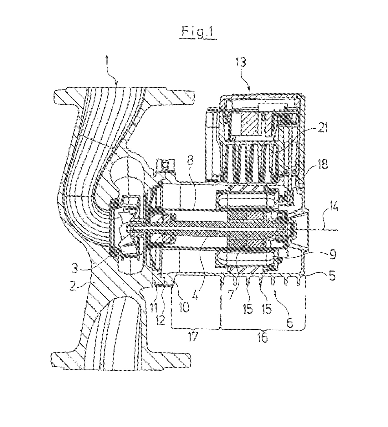
[0024]Referring to the drawings in particular, the centrifugal pump assembly represented by way of FIG. 1 comprises a centrifugal pump 1 with a pump housing 2 and with an impeller 3 which is rotatably arranged therein and which is seated on a shaft 4 of a motor housing 5 of an electric motor 6 which connects to the pump housing 2. With regard to the electric motor 6 it is the case of a wet-running motor, i.e. the space, in which the rotor 7 runs with the shaft 4, is filled with fluid and is separated from the stator 9 in a fluid-tight manner by a can 8. The stator 9 is seated in the motor housing 5 which is circular in cross section and which is releasably connected by way of a flange 10 to a flange 11 of the pump housing via a clamping ring 12.

[0025]With regard to the electric motor, it is the case of a permanent magnet rotor which is activated by an electronic speed controller which is arranged in an electronics housing 13 which is fastened in the manner of a terminal box on the m...


PUM


Abstract

An electric motor includes a motor housing (5) which includes cooling ribs (15) on the peripheral side leading away heat arising in the motor. The cooling ribs (15) only extend over a part of the periphery of the motor housing (5), so that cooling ribs (21) of the electronics housing (13) have space in the cooling-rib-free part of the motor housing (5). The cooling ribs (21) of the electronics housing (13) are arranged aligned with the cooling ribs (15) of the motor transversely to a motor axis (14).

Description

CROSS REFERENCE TO RELATED APPLICATIONS[0001]This application is a United States National Phase Application of International Application PCT / EP2013 / 052369 filed Feb. 7, 2013 and claims the benefit of priority under 35 U.S.C. § 119 of European Patent Application EP 12154494.4 filed Feb. 8, 2012, the entire contents of which are incorporated herein by reference.FIELD OF THE INVENTION[0002]The invention relates to an electric motor, in particular wet-running motor for the drive of a centrifugal pump, with a rotor, with a motor shaft which is rotatably arranged in a stator comprising motor windings, with a motor housing which receives the stator and which comprises cooling ribs on a peripheral side for leading away heat arising in the motor.BACKGROUND OF THE INVENTION[0003]It is counted as belonging to the state of the art, to provide electric motors with cooling ribs over the complete periphery of their motor housing, in order to lead away waste heat occurring in the electric motor on ...

Claims


Application Information

Patent Timeline
Patent Type & Authority Patents(United States)
IPC IPC(8): H02K5/00H02K9/19H02K5/22F04D13/06F04D29/58H02K5/18H02K11/33H02K5/128H02K7/14
CPCH02K5/18F04D13/06F04D29/5806F04D29/5813H02K9/19H02K11/33H02K5/22H02K7/14H02K5/128
Inventor MIKKELSEN, KNUD JORGEN SAABYBREITZKE, BJORNHEELUND, STEEN
Owner GRUNDFOS HLDG
Why Eureka
Try Eureka