
Refraction technology system

a technology of refraction and refraction technology, applied in water treatment compounds, water/sewage treatment by electrochemical methods, water treatment multi-stage treatments, etc., can solve the problem that the modified fluids will naturally return to the orp, and achieve the effect of efficient production of modified orp fluids, efficient and chemical-free cleansing and rinsing techniques, and superior results

Active Publication Date: 2019-04-02
BARRETT RICHARD J +1
View PDF3 Cites 0 Cited by
  • Summary
  • Abstract
  • Description
  • Claims
  • Application Information

AI Technical Summary

Benefits of technology

The system efficiently produces modified ORP fluids that maintain their altered levels for longer durations, providing effective chemical-free cleansing and disinfecting capabilities, as demonstrated by superior results in cleaning and disinfecting applications without using harsh chemicals.

Problems solved by technology

It is known that conventional ORP modified fluids will naturally return toward a neutral ORP level over time, oftentimes very rapidly.

Method used


Image

  • Refraction technology system
  • Refraction technology system
  • Refraction technology system

Examples


example 1

[0031]In Example 1, suspensions of Pseudomonas aeruginosa (Sample A), Salmonella sp (Sample B), Listeria monocytogenes (Sample C), Staphylococcus aureus (Sample D), Escherichia coli (Sample E) and Serratia marcescens (Sample F) were prepared and diluted to 100,000 fu / mL for inoculation. The level of each 6 inoculum suspension was tested by plating a dilution of the suspension containing 100 cfu / mL.

[0032]For each bacteria suspension (A-F), three 100 mL samples were prepared for comparative purposes. Each 100 mL sample was inoculated with 100,000 colony forming units (cfu) of the appropriate bacteria, resulting in 1,000 cfu of bacteria per mL of sample.

[0033]Each sample was then mixed with modified fluid prepared using the disclosed system 10 and method with an ORP value of approximately +700. The samples of each bacteria were tested at different intervals from the time of mixing with modified fluid: 1 mL of each sample was removed at 30 seconds, 2 minutes, 5 minutes and 10 minutes me...

example 2

[0036]FIG. 4 shows a photo time table depicting a test screen cleaning using the modified fluid treated with the disclosed oxidation refraction system 10. Fluid samples from the negative chamber (+700 ORP) were tested and displayed varying degrees of effectiveness.

[0037]FIG. 4A depicts the fully contaminated and dried filtration screen to be treated. FIG. 4B depicts the screen of FIG. 4A approximately 5 seconds after an initial rinse with the oxidized fluid. FIG. 4C depicts the screen 15 seconds after the initial rinse with oxidized fluid. FIG. 4D depicts the screen 20 seconds after the initial rinse. FIG. 4E depicts a fully cleaned screen, less than 30 seconds after the initial rinse with oxygen modified fluid. FIG. 4E further shows that the fluid draining from the filter is clear in appearance (clean).

[0038]The actual experimental photos shown in FIGS. 4A-4E and described above are an example of a test performed to eliminate the buildup and bacteria on a filtration screen used for...


PUM

PropertyMeasurementUnit
thickaaaaaaaaaa
currentaaaaaaaaaa
voltageaaaaaaaaaa

Abstract

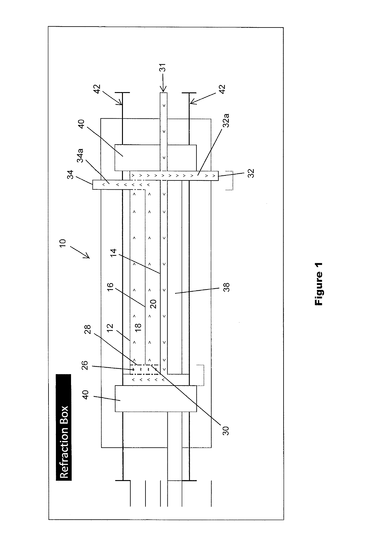
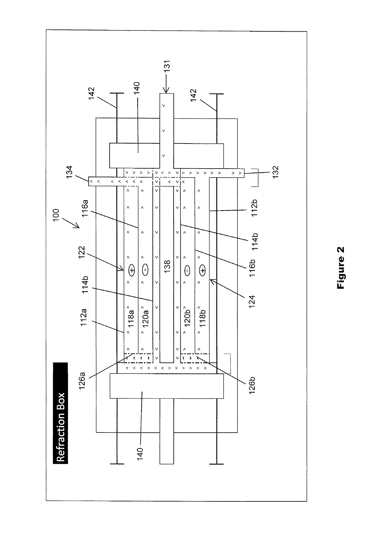
A system and method for modifying monoatomic oxygen levels in an initial fluid, for applications. The system and method produces both positive and negative oxygen modified fluid that retains oxygen levels for long durations as measured by oxygen reduction potential (ORP). An incoming fluid is split between a positive chamber defined by a cathode and a porous divider and a negative chamber defined by the porous divider and an anode. The relative charge over the porous divider produces fluid with elevated ORP from the positive chamber and fluid with lowered ORP from the negative chamber. A method of killing bacteria includes contacting the bacteria with negative ORP fluid produced in the system and method to the bacteria.

Description

CROSS-REFERENCE TO RELATED APPLICATION[0001]This application claims priority from U.S. Provisional Patent Application No. 62 / 201,236 filed Aug. 5, 2015, the entire content of which is incorporated herein by reference.BACKGROUND OF THE DISCLOSURE[0002]The disclosure relates to fluid modification. More particularly, the disclosure relates to a refraction system and method for modifying fluid to produce high (i.e., “positive”) and / or low (i.e., “negative”) oxygen content fluid.[0003]A complete understanding of the disclosed system may be obtained by reference to the accompanying drawings, when considered in conjunction with the subsequent, detailed description, in which the technology was primarily designed for the flushing and rinse cleaning of the clogged and embedded materials captured on filtering screens, hard surfaces, of all materials or similar applications, as shown in the photographs of FIG. 4. The disclosed refraction technology oxidation reduction potential, (ORP) modificat...

Claims


Application Information

Patent Timeline
Patent Type & Authority Patents(United States)
IPC IPC(8): A61L9/00A61L2/00A61L2/03C02F1/46A62B7/08C02F1/461A61L2/02C02F1/32
CPCA61L2/035C02F1/4602A61L2202/11A61L2202/17C02F1/325C02F2201/46115C02F2305/023C02F2209/04C02F2301/08C02F2303/04C02F2303/14C02F2303/20C02F2201/46125
Inventor BARRETT, RICHARD J.CARSTENSEN, MICHAEL
Owner BARRETT RICHARD J
Learn More