Tool holding fixture

Active Publication Date: 2019-04-02
HAIMER
View PDF20 Cites 0 Cited by
  • Summary
  • Abstract
  • Description
  • Claims
  • Application Information

AI Technical Summary

Benefits of technology

[0022]In order to be able to attach the sleeve 11 more easily, the holding body in one advantageous embodiment can have guide surfaces or similar elements to facilitate the positioning in the best possible way. Such a guide surface may be, for example, a flattened mating surface on the otherwise round outside diameter of the holding body 3, which finds its corresponding counter surface in the sleeve 11. Such a measure also ensures that the connecting points provided as a br

Problems solved by technology

However, since the holding body, made of steel, has to have certain dimensions in order to achieve the required rigidi

Method used


Image

  • Tool holding fixture
  • Tool holding fixture
  • Tool holding fixture

Examples


Example

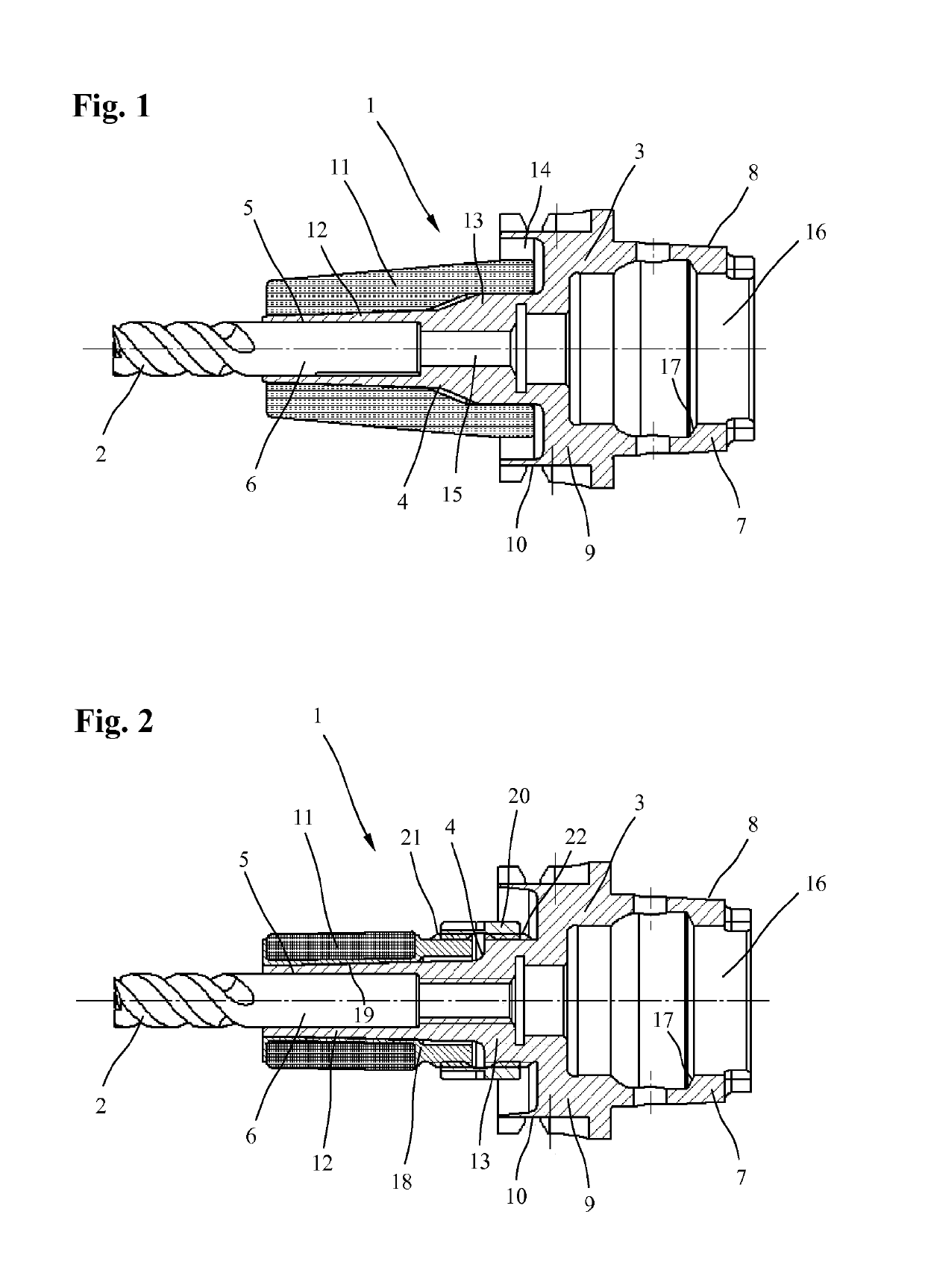
[0032]FIG. 1 shows a tool holding fixture 1, which is provided in this embodiment with an FISK interface, for non-positive holding of drilling, milling, reaming tools or any other rotationally driven tools 2, in the embodiment shown, the tool holding fixture 1 is designed as a thermal chuck and includes a rotationally symmetrical holding body 3, which on its tool-sided front end has a damping region 4 with a receiving opening 5 for a tool shank 6 of the tool 2 and on its machine-sided rear end has a rear holding region 7, which is conical in this embodiment and has a conical outer clamping surface 8 to be held in a work spindle of a machine tool. Furthermore the holding body 3, made of steel, also has a cylindrical central region 9 with a gripper groove 10 for engagement with a tool changer. A sleeve 11, made of a carbon fiber reinforced plastic (CFRP) or any other fiber reinforced plastic, is disposed on the front clamping region 4 of the holding body 3.

[0033]In the embodiment show...


PUM

PropertyMeasurementUnit
Stiffnessaaaaaaaaaa

Abstract

The invention relates to a tool holding fixture (1) for rotationally driven tools (2), said tool holding fixture comprising a rotationally symmetrical holding body (3) which has a front clamping portion (4) having a holding opening (5) for a tool shaft (6) of the tool (2), and a rear holding portion (7) to be held in a work spindle of a machine tool. To achieve a reduced mass, a lower mass moment of inertia and at the same time high stiffness, a sleeve (11) consisting of a fiber-reinforced plastic is arranged at least in the front clamping portion (4).

Description

PRIORITY CLAIM[0001]This application claims priority from German Patent Application No. 10 2013 108 209.2 filed Jul. 31, 2013, and International Patent Application PCT / EP2014 / 066466 filed Jul. 31, 2014.BACKGROUND OF THE INVENTION[0002]The invention relates to a tool holding fixture for rotationally driven tools.[0003]Tool holding fixtures of this type are used as an interface between a rotationally driven tool and a work spindle of a machine tool. They are supposed to allow the tools to be held precisely in position for machining with hid accuracy and quick tool changes. The tool holding fixtures, known from the prior art, typically comprise a holding body that is made of steel and that includes a front clamping region with a receiving opening for a tool shank of the tool and a rear holding region to be held in a work spindle of a machine tool. Depending on the clamping system, the rear holding region may be designed in different ways. However, since the holding body, made of steel,...

Claims


Application Information

Patent Timeline
IPC IPC(8): F16B4/00B23P11/02B23B31/117
CPCB23B31/1179B23B31/117B23P11/025F16B4/006Y10T279/17957B23B2231/24B23B2240/28Y10T29/49865Y10T279/17111B23B2226/275
Inventor POPP, KONRADELGES, JOHANNHEDRICH, RENEEMERK, ROBERTKLINGER, JURGEN
Owner HAIMER
Why Eureka
Try Eureka