
Electric motor control apparatus and electric motor control method

a technology of electric motors and control apparatuses, applied in control systems, electric commutators, road transportation emission reduction, etc., can solve the problems of increasing the loss due to the switching operation of each switching element, and the increase of the ripple in the terminal voltage of the smoothing capacitor. , to achieve the effect of increasing the ripple in the terminal voltage of the smoothing capacitor, increasing the priority, and increasing the ripple

Active Publication Date: 2019-04-02
DENSO CORP
View PDF18 Cites 2 Cited by
  • Summary
  • Abstract
  • Description
  • Claims
  • Application Information

AI Technical Summary

Benefits of technology

This approach effectively reduces the number of switching operations and associated losses in the power converter, while also managing the ripple in the terminal voltage of smoothing capacitors, enhancing the overall efficiency of the motor control system.

Problems solved by technology

However, if the capacitance of the smoothing capacitor is reduced, there is a concern that a ripple (so-called pulsation component) in the terminal voltage of the smoothing capacitor relatively increases.
In such a power converter, there arises a loss due to switching (that is, switching operation) of the state of each of the switching elements.
The loss due to the switching operation of each switching element increases as the number of switching operations of each switching element per unit time increases.
However, in the techniques described in JP 2010-263775 A and JP 2004-120853 A, there is a technical inconvenience that it is not possible to sufficiently reduce the number of switching operations of each switching element because a principal object is to suppress a ripple in the terminal voltage of the smoothing capacitor.

Method used


Image

  • Electric motor control apparatus and electric motor control method
  • Electric motor control apparatus and electric motor control method
  • Electric motor control apparatus and electric motor control method

Examples


Embodiment Construction

[0050]Hereinafter, an embodiment of an electric motor control apparatus will be described.

(1) Configuration of Vehicle

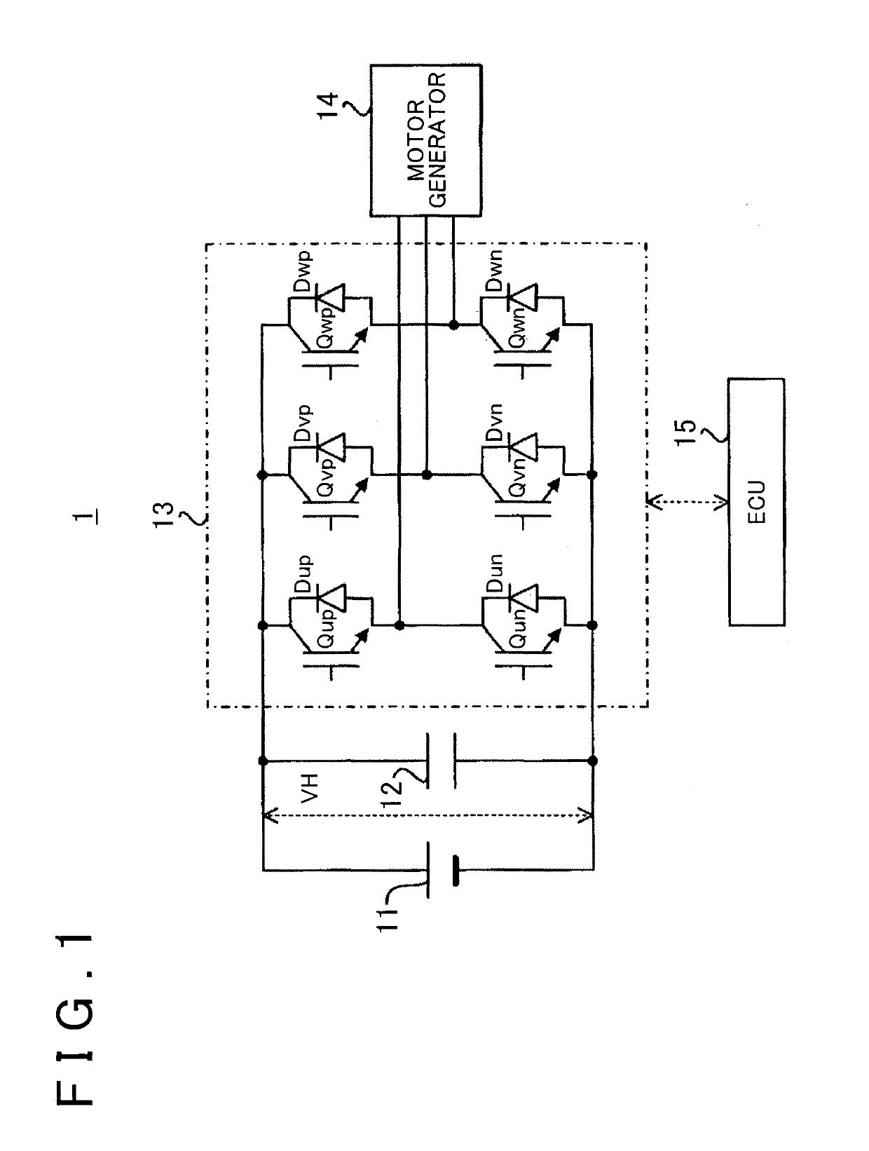
[0051]The configuration of a vehicle 1 will be described with reference to FIG. 1. FIG. 1 is a block diagram that shows the configuration of the vehicle 1.

[0052]As shown in FIG. 1, the vehicle 1 includes a direct-current power supply 11, a smoothing capacitor 12, an inverter 13, a motor generator 14, and an electronic control unit (ECU) 15. The inverter 13 is an example of a “power converter”. The motor generator 14 is an example of a “three-phase alternating-current motor”. The ECU 15 is an example of an “electric motor control apparatus”.

[0053]The direct-current power supply 11 is a rechargeable electrical storage device. For example, a secondary battery (such as a nickel-metal hydride battery and a lithium ion battery) and a capacitor (such as an electric double layer capacitor and a large-capacitance capacitor) are illustrated as an example of the direct-current ...


PUM


Abstract

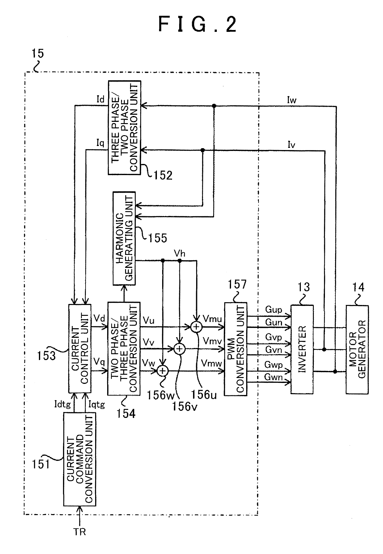
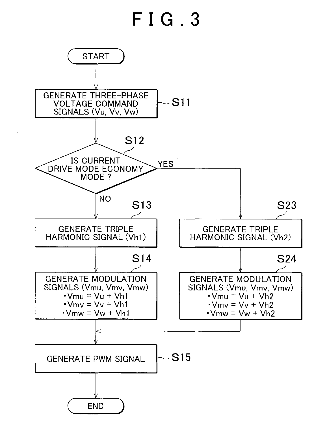
An electric motor control apparatus controls an electric motor system that includes a power converter including switching elements and a three-phase alternating-current motor. The electric motor control apparatus includes generating devices for generating modulation signals by respectively adding corresponding triple harmonic signals to phase voltage command signals and a control device for controlling switching elements on the basis of a magnitude relation between each of the modulation signals and a carrier signal. Each of the triple harmonic signals includes a signal component that increases the absolute value of a peak value of a signal level of the corresponding modulation signal above the absolute value of a peak value of a signal level of the carrier signal in a corresponding one of phases.

Description

CROSS-REFERENCE TO RELATED APPLICATIONS[0001]This is a national phase application based on the PCT International Patent Application No. PCT / IB2014 / 001778 filed Sep. 10, 2014, claiming priority to Japanese Patent Application No. 2013-188219 filed Sep. 11, 2013, the entire contents of both of which are incorporated herein by reference.BACKGROUND OF THE INVENTION[0002]1. Field of the Invention[0003]The invention relates to an electric motor control apparatus that controls an electric motor system including, for example, a three-phase alternating-current motor.[0004]2. Description of Related Art[0005]There is pulse width modulation (PWM) control as an example of a control method to drive a three-phase alternating-current motor. In PWM control, a power converter that converts a direct-current voltage (direct-current power) to alternating-current voltages (alternating-current powers) is controlled on the basis of a magnitude relation between each of phase voltage command signals and a car...

Claims


Application Information

Patent Timeline
Patent Type & Authority Patents(United States)
IPC IPC(8): H02P6/14H02P27/06H02P6/08H02P27/08H02P6/10
CPCH02P6/10H02P6/08H02P27/08H02P27/06Y02T10/84
Inventor YAMAKAWA, TOSHIFUMIOKAMURA, MASAKITAKAMATSU, NAOYOSHI
Owner DENSO CORP
Learn More